Combustion turbine engine and methods of assembly

a combustion turbine and combustion turbine technology, applied in the direction of combustion types, turbine/propulsion engine ignition, lighting and heating apparatus, etc., can solve problems such as stress in brazed joints

Inactive Publication Date: 2007-07-05
GENERAL ELECTRIC CO
View PDF15 Cites 87 Cited by
  • Summary
  • Abstract
  • Description
  • Claims
  • Application Information

AI Technical Summary

Benefits of technology

[0005] In one aspect, a method of assembling a combustion turbine engine in provided. The method includes coupling at least one fuel nozzle inner atomized air tube to a combustor end cover plate body, and assembling a fuel nozzle insert sub-assembly by inserting at least one flow control apparatus into a fuel nozzle insert sub-assembly body. The method further includes inserting at least one seal between the combustor end cover plate body and the fuel nozzle insert sub-assembly body, and within at least a portion of an annular diffusion fuel passage, and inserting at least one seal between the combustor end cover plate body and the fuel nozzle insert sub-assembly body, and within at least a portion of a pre-orifice premix fuel annulus. The method also includes coupling the fuel nozzle insert sub-assembly body to the combustor end cover plate body, inserting at least one bellows onto a bellows support fitting, inserting the bellows support fitting onto a fuel nozzle insert sub-assembly body support surface, and assembling a fuel nozzle sub-assembly by coupling at least one radially outer tube, at least one radially inner tube, at least one intermediate tube, and at least one fuel nozzle mounting flange. The method further includes assembling a fuel nozzle assembly by coupling the fuel nozzle sub-assembly to the combustor end cover plate body.
[0006] In another aspect, a fuel nozzle assembly is provided. The fuel nozzle assembly includes a combustor end cover sub-assembly, at least one fuel nozzle insert sub-assembly and a fuel nozzle sub-assembly. The cover sub-assembly includes a combustor end cover plate body. The insert sub-assembly includes an insert body and at least one flow control apparatus. The fuel nozzle sub-assembly includes at lest one tube. The fuel nozzle assembly also includes a plurality of seals. The seals are inserted between the insert body, the end cover plate body and the tube wall.

Problems solved by technology

Therefore, the large range of temperature variations in conjunction with the differing thermal expansion and contraction properties of the fuel nozzle assemblies materials causes stresses in the brazed joints, including the brazed joints associated with combustor end covers and fuel nozzle inserts.

Method used


Image

  • Combustion turbine engine and methods of assembly
  • Combustion turbine engine and methods of assembly
  • Combustion turbine engine and methods of assembly

Examples


Embodiment Construction

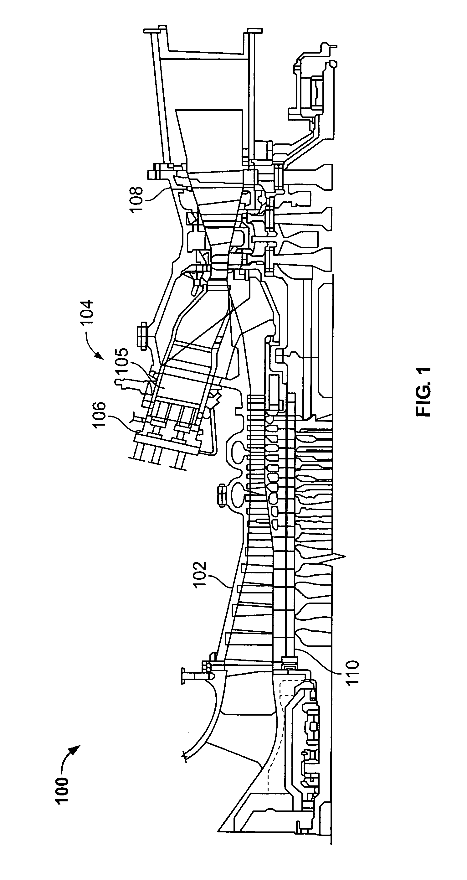
[0012]FIG. 1 is a schematic illustration of an exemplary combustion turbine engine 100. Engine 100 includes a compressor 102 and a combustor 104. Combustor 104 includes a combustion region 105 and a fuel nozzle assembly 106. Engine 100 also includes a turbine 108 and a common compressor / turbine shaft 110 (sometimes referred to as rotor 110). In one embodiment, engine 100 is a MS7001FB engine, sometimes referred to as a 7FB engine, commercially available from General Electric Company, Greenville, S.C. The present invention is not limited to any one particular engine and may be implanted in connection with other engines including, for example, the MS7001FA (7FA), MS9001FA (9FA), and MS9001FB (9FB) engine models of General Electric Company.

[0013] In operation, air flows through compressor 102 and compressed air is supplied to combustor 104. Specifically, a substantial amount of the compressed air is supplied to fuel nozzle assembly 106 that is integral to combustor 104. Some combustor...


PUM


Abstract

A method of assembling a combustion turbine engine in provided. The method includes coupling at least one fuel nozzle inner atomized air tube to a combustor end cover plate body. The method also includes assembling a fuel nozzle insert sub-assembly by inserting at least one flow control apparatus into a fuel nozzle insert sub-assembly body. The method further includes inserting at least one seal between the combustor end cover plate body and the fuel nozzle insert sub-assembly body as well as inserting at least one seal between the combustor end cover plate body and the fuel nozzle insert sub-assembly body. The method also includes coupling the fuel nozzle insert sub-assembly to the combustor end cover plate body. The method further includes inserting at least one bellows onto a bellows support fitting and inserting the bellows support fitting onto a fuel nozzle insert sub-assembly body support surface. The method also includes assembling a fuel nozzle sub-assembly. The method further includes assembling a fuel nozzle assembly by coupling the fuel nozzle sub-assembly to the combustor end cover plate body.

Description

BACKGROUND OF THE INVENTION [0001] This invention relates generally to rotary machines and more particularly, to methods and apparatus for assembling combustion turbine engines. [0002] Many known combustion turbine engines ignite a fuel-air mixture in a combustor and generate a combustion gas stream that is channeled to a turbine via a hot gas path. Compressed air is channeled to the combustor by a compressor. Combustor assemblies typically have fuel nozzles that facilitate fuel and air delivery to a combustion region of the combustor. The turbine converts the thermal energy of the combustion gas stream to mechanical energy that rotates a turbine shaft. The output of the turbine may be used to power a machine, for example, an electric generator or a pump. [0003] Many known fuel nozzle assemblies have a variety of components manufactured from a variety of materials that are joined together with brazed joints. These materials, including the brazed joints, may have differing thermal gr...

Claims


Application Information

Patent Timeline
Patent Type & Authority Applications(United States)
IPC IPC(8): F23R3/20
CPCF23D14/48F23D2211/00F23R2900/00012F23R2900/00001F23R3/286
Inventor JOHNSON, THOMAS EDWARDBROWN, JAMES THOMAS
Owner GENERAL ELECTRIC CO
Why Eureka
Try Eureka