Detection, location, and characterization of buried explosive devices and weapon caches
a technology of explosive devices and caches, applied in the field of buried explosive devices and weapons caches, can solve the problems of ineffective detection, location, and characterization of potentially dangerous explosive devices concealed or buried in the prior ar
- Summary
- Abstract
- Description
- Claims
- Application Information
AI Technical Summary
Problems solved by technology
Method used
Image
Examples
first embodiment
A FIRST EMBODIMENT
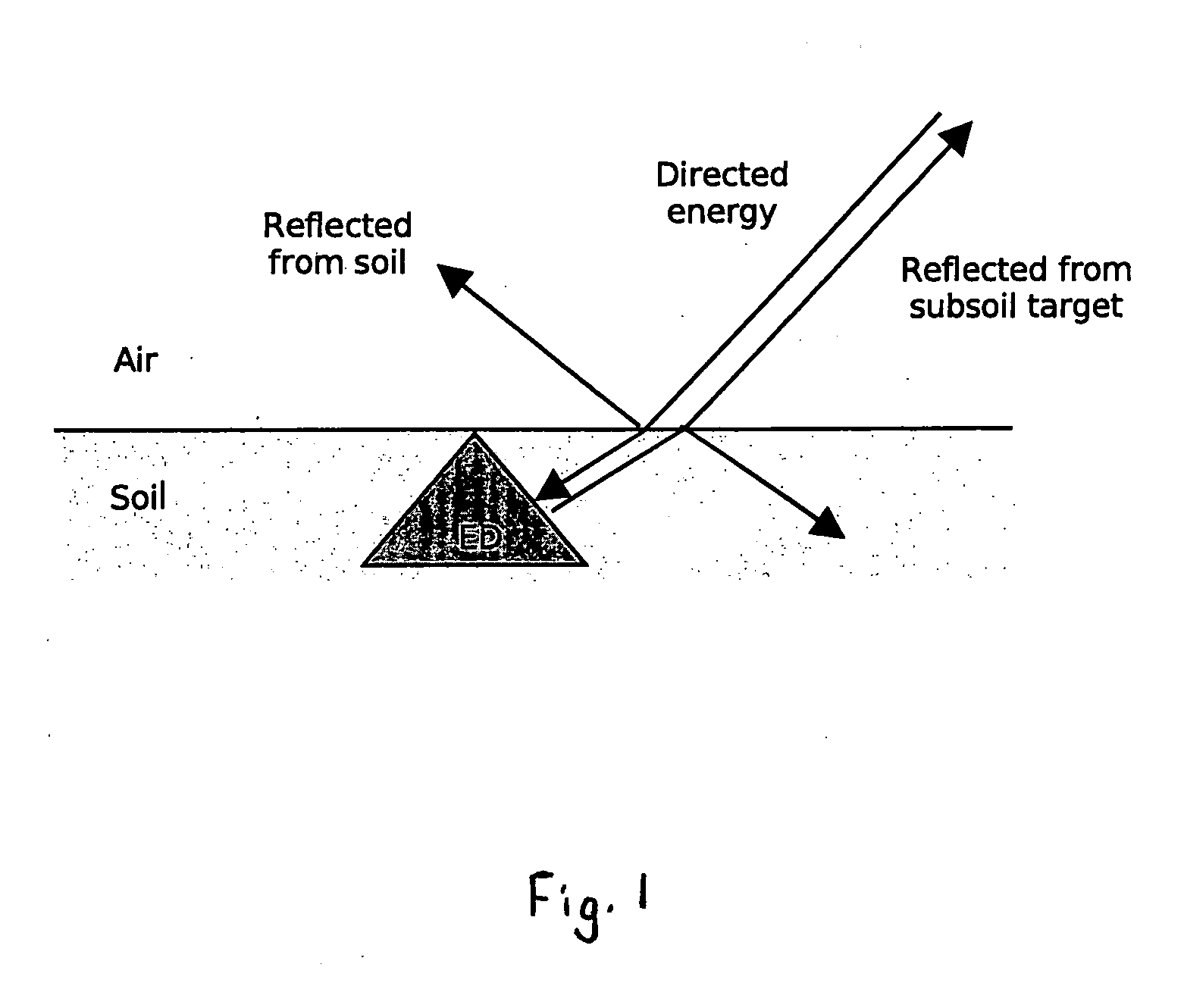
[0024] In one embodiment of this invention, buried objects are detected and characterized as follows. A probe emits an energy wave, preferably utilizing equipment and techniques well known in the relevant art. The energy wave used is preferably acoustic or microwave; however, other portions of the electromagnetic spectrum may be employed. The probe energy wave is directed towards the ground at an incident angle such that the ground surface reflection is not towards the detector array (FIG. 1). Measurements are taken of reflections received at the detector, preferably utilizing equipment and techniques well known in the relevant art. Any surfaces of the buried object which are directed towards the detector provide reflections with minimal background from the ground surface reflection and that are thereby more easily detected and measured. These reflection-based measurements may be corrected for refraction at the ground surface (i.e., ground-air interface).
[0025] Th...
second embodiment
A SECOND EMBODIMENT
[0026] Another embodiment of this invention comprises introducing underground a probe energy wave, preferably utilizing equipment and techniques well known in the relevant art. Preferably, the energy wave is acoustic; however, electromagnetic probe energy may be employed. A sensor array is introduced underground to receive the wave reflected by the target object through the soil, preferably utilizing equipment and techniques well known in the relevant art. The probe preferably comprises one or more transmitting transducers and three or more receiving transducers. Theoretically, two receiving transducers are sufficient to locate objects and measure the net reflected energy in the direction from the object to the receivers. Similarly, three receiving transducers are sufficient to measure the size and normalized reflectivity of the object when the receiver array is located in the central portion of the reflected wave. Objects are located by any combination of triangu...
third embodiment
A THIRD EMBODIMENT
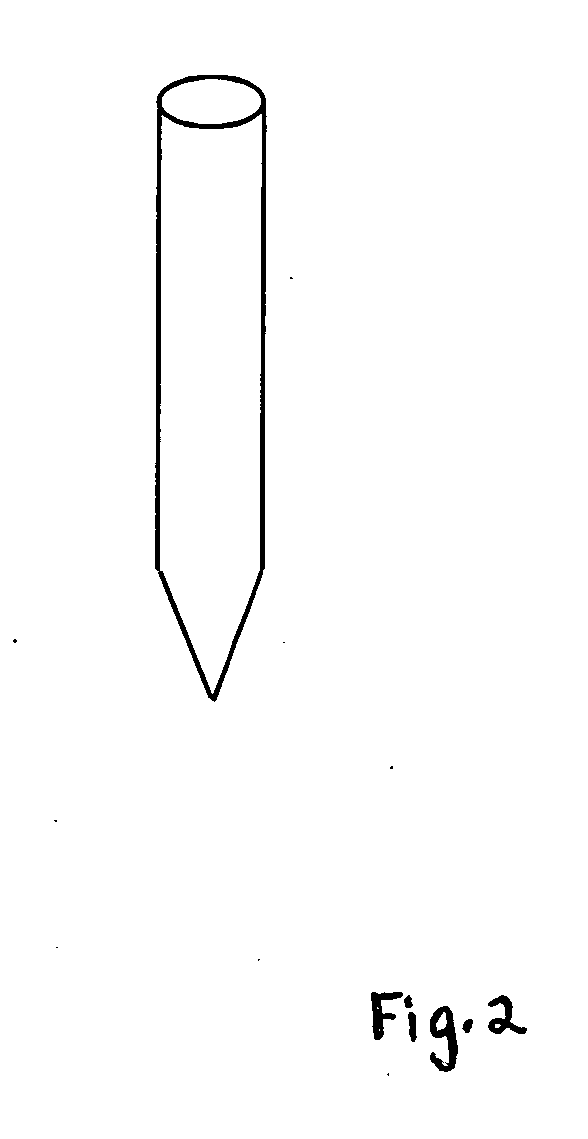
[0027] Another embodiment of this invention comprises an ultrasonic transducer for subsoil ultrasound detection and location of various objects including weapons and explosive devices. The transducer is preferrably constructed in a firm or hard housing material, drawn or sharpened to a point so that it can be jabbed into the ground, and the transducer is provided with a matching layer to match as closely as practical, the acoustic impedance of the range of soils that the transducer will be used in, preferably utilizing equipment and techniques well known in the relevant art.
PUM
 Abstract
Description
Claims
Application Information
 - R&D
- Intellectual Property
- Life Sciences
- Materials
- Tech Scout
- Unparalleled Data Quality
- Higher Quality Content
- 60% Fewer Hallucinations
Browse by: Latest US Patents, China's latest patents, Technical Efficacy Thesaurus, Application Domain, Technology Topic, Popular Technical Reports.
© 2025 PatSnap. All rights reserved.Legal|Privacy policy|Modern Slavery Act Transparency Statement|Sitemap|About US| Contact US: help@patsnap.com


