Microinjection apparatus integrated with size detector

Inactive Publication Date: 2007-07-05
BENQ CORP
View PDF3 Cites 59 Cited by
  • Summary
  • Abstract
  • Description
  • Claims
  • Application Information

AI Technical Summary

Benefits of technology

[0007] The invention provides a microinjection apparatus integrated with a size detector to detect the size of a fluid chamber, and further, to judge the fluid-filled condition in the fluid chamber. Moreover, the det

Problems solved by technology

Although the size of the microinjection apparatus diminishes as technology develops, the structure of the microinjection apparatus is more and more complicated.
It is very time-consuming and cost-consuming.
However, many

Method used


Image

  • Microinjection apparatus integrated with size detector
  • Microinjection apparatus integrated with size detector
  • Microinjection apparatus integrated with size detector

Examples


Embodiment Construction

[0018] The invention provides a microinjection apparatus and, more particularly, a microinjection apparatus integrated with a size detector. According to this invention, several preferred embodiments are disclosed as follows.

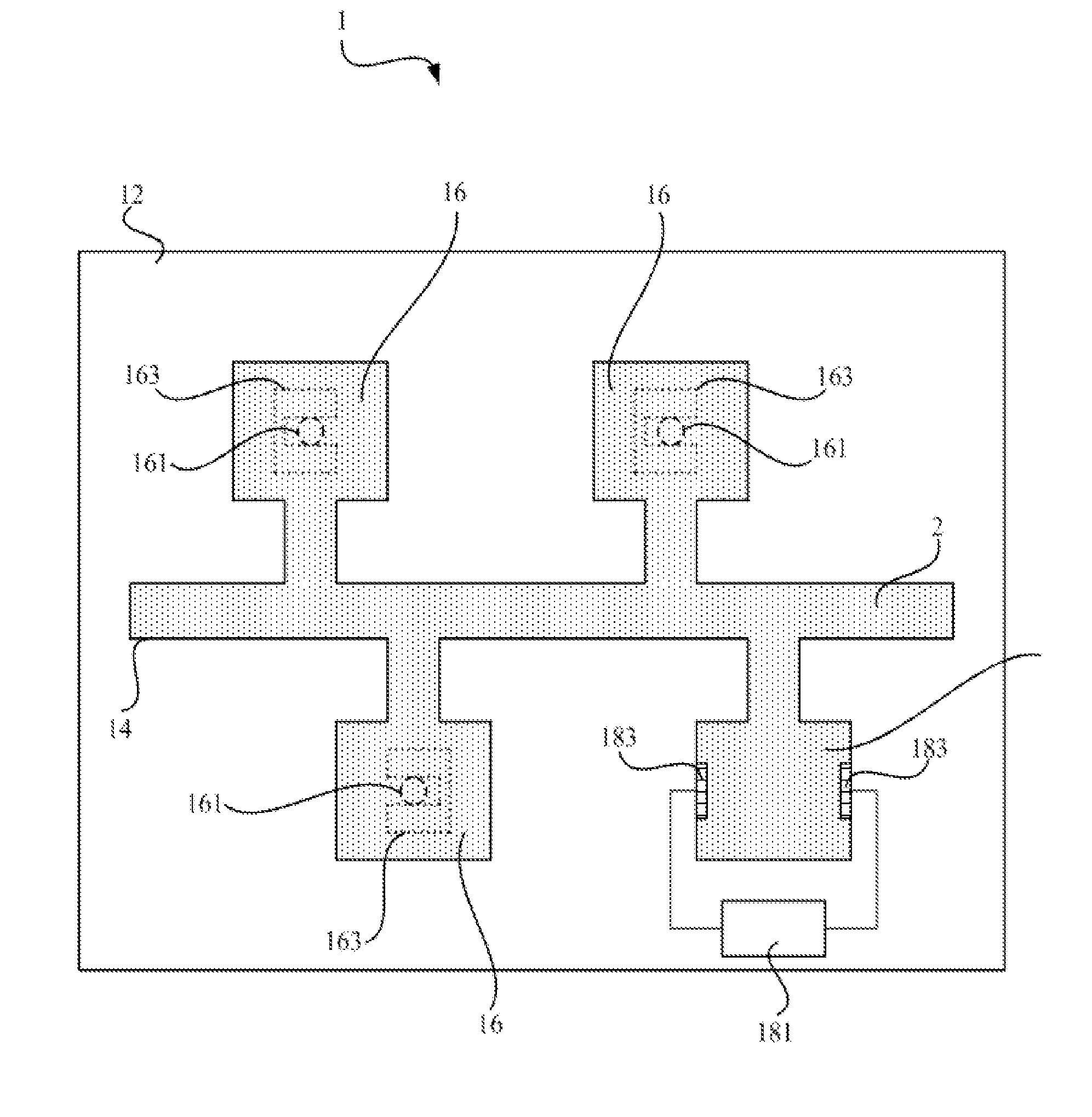
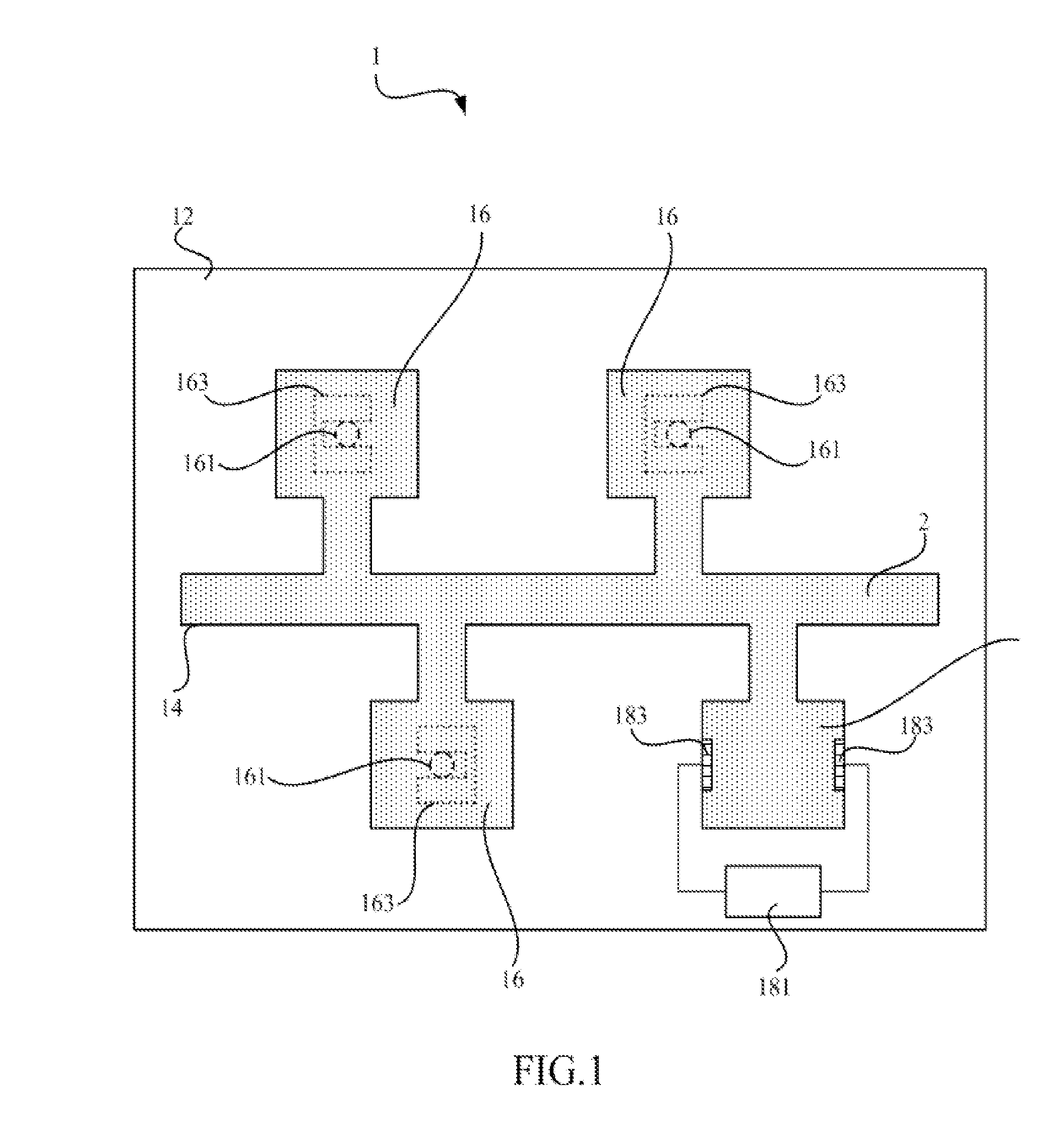
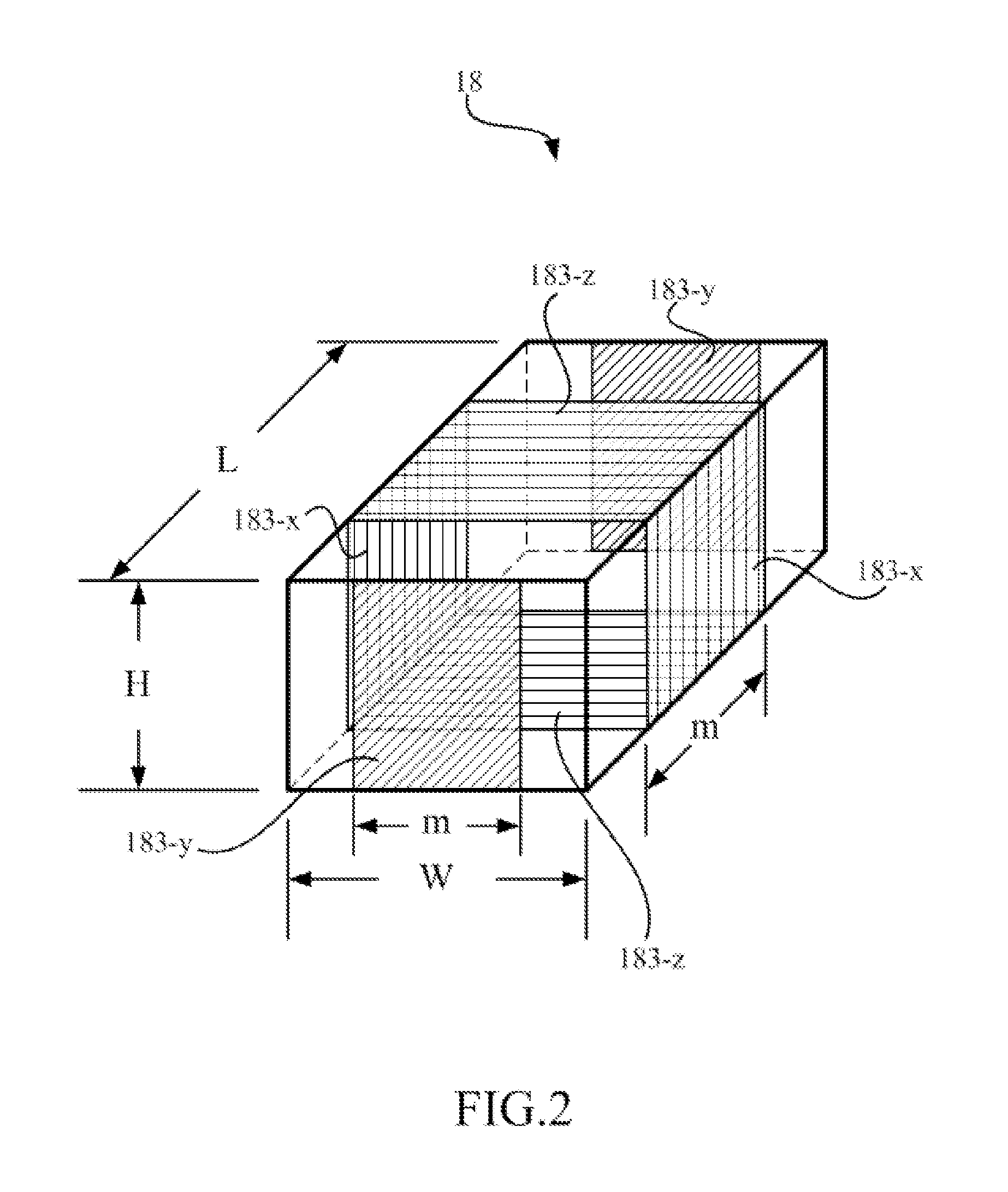
[0019] Referring to FIG. 1, FIG. 1 is a schematic diagram of a microinjection apparatus 1 according to a preferred embodiment of the invention. According to this first preferred embodiment, the microinjection apparatus 1 for a fluid 2 includes a substrate 12, a manifold 14, at least one fluid chamber 16, at least one dummy chamber 18, a detecting device 181, and at least one pair of parallel conductive plates 183.

[0020] The manifold 14 is formed on the substrate 12, used for containing the fluid 2 therein, and used for supplying the liquid 2 to at least one fluid chamber 16 and at least one dummy chamber 18, which are all formed on the substrate 12 and in communication with the manifold 14. Each of the at least one fluid chamber 16 has at least one orifice 161...


PUM


Abstract

The invention provides a microinjection apparatus for a fluid. The microinjection apparatus includes a substrate, a manifold, a fluid chamber, a dummy chamber, a detecting device, and a pair of parallel conductive plates. The manifold is formed on the substrate and supplies the fluid chamber and the dummy chamber, also formed on the substrate, with the fluid. In addition, the pair of parallel conductive plates are formed on a pair of opposite inner walls of the dummy chamber, and electrically connected to the detecting device. By applying the pair of parallel conductive plates and the detecting device provided in the invention, the size of the fluid chamber and the fluid-filled condition relative to the fluid chamber can be indirectly detected by non-destructive testing. Furthermore, the cost of and the time of testing also can be prominently saved.

Description

BACKGROUND OF THE INVENTION [0001] 1. Field of the Invention [0002] The invention relates to a microinjection apparatus and, more particularly, to a microinjection apparatus integrated with a size detector. [0003] 2. Description of the Prior Art [0004] Micro-technology has a revolutionary impact on many technical fields, such as information industry, communication industry, consumer electronic industry, and bio-technology industry. It is also expected to continuously improve the technology in the production and manufacture in these fields. In these kinds of technology, the microfluidic system relates to the designing, constructing, and manufacturing the device and the process regarding operating micro fluid. At present, the microinjection apparatus, which is one of the microfluidic systems generally used, is extensively used in many techniques including ink-jet printer, biochemical testing, drug screening, fuel injection system, chemical synthesis, and so forth. [0005] Although the ...

Claims


Application Information

Patent Timeline
IPC IPC(8): B41J2/195
CPCB41J2/14153
Inventor CHOU, CHUNG-CHENGWANG, WILLIAM
Owner BENQ CORP
Why Eureka
Try Eureka