Imaging device and method for displaying shooting mode

a technology of a shooting mode and an imager, which is applied in the field of imaging devices, can solve the problems of complicated operation and difficulty for many general users to sufficiently understand the shooting properties of the respective shooting mode, and achieve the effect of convenient us

Inactive Publication Date: 2007-07-05
FUJIFILM CORP
View PDF8 Cites 37 Cited by
  • Summary
  • Abstract
  • Description
  • Claims
  • Application Information

AI Technical Summary

Benefits of technology

[0005] In view of the foregoing, it is a primary object of the present invention to provide an imaging device in which a manual mode is easily utilized.
[0012] It is preferable that data of the through image is used as the pre-image data. By doing so, a time-lag of a shooting time is reduced.
[0016] According to the present invention, the manual mode is easily used and it is possible to set the optimum shooting conditions corresponding to the shooting scene. Furthermore, it is possible to take a picture on the optimum shooting conditions corresponding to the shooting scene.

Problems solved by technology

However, it is difficult for many general users to sufficiently understand shooting properties of the respective shooting mode.
In addition, operations are complicated.

Method used


Image

  • Imaging device and method for displaying shooting mode
  • Imaging device and method for displaying shooting mode
  • Imaging device and method for displaying shooting mode

Examples


Embodiment Construction

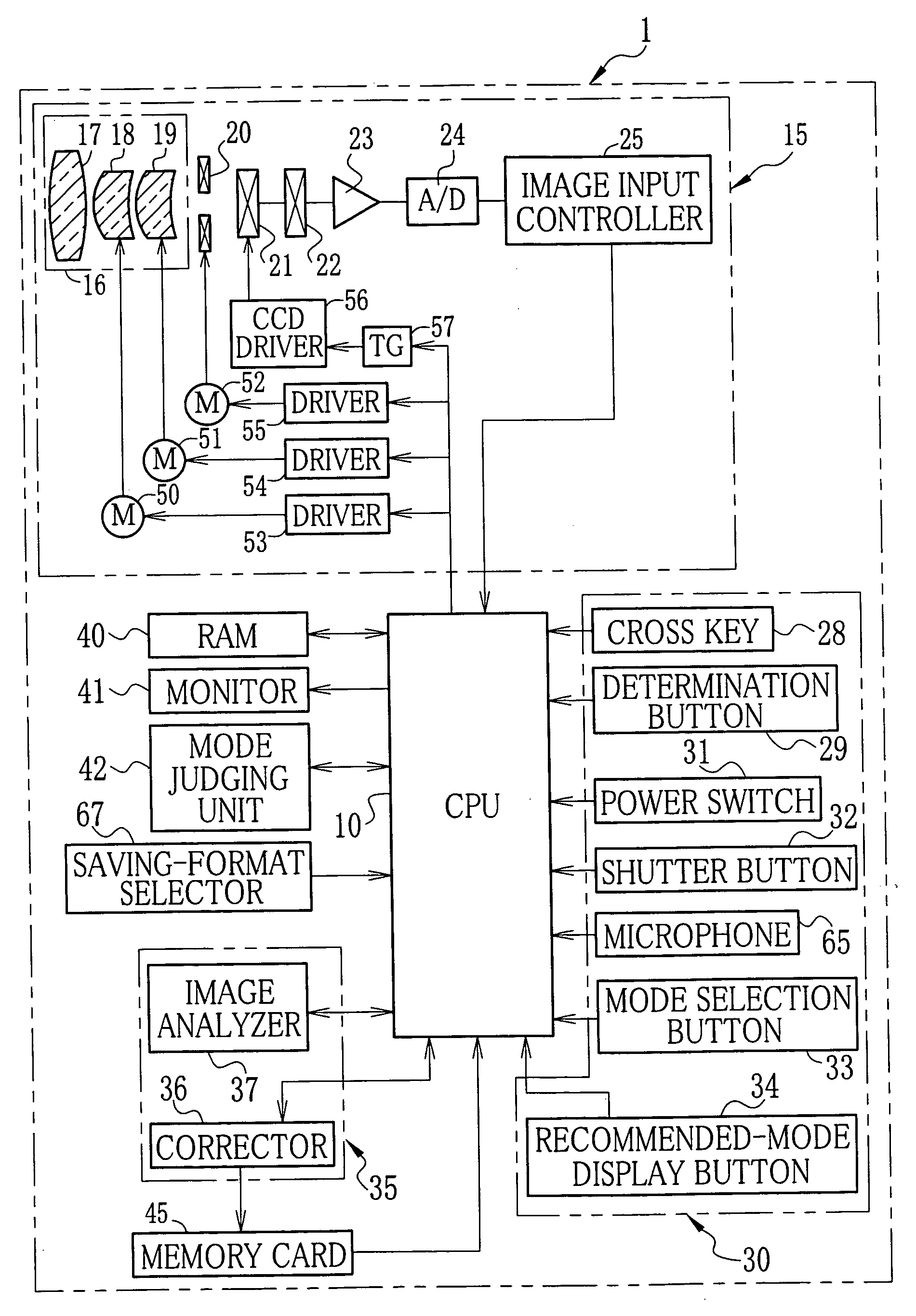
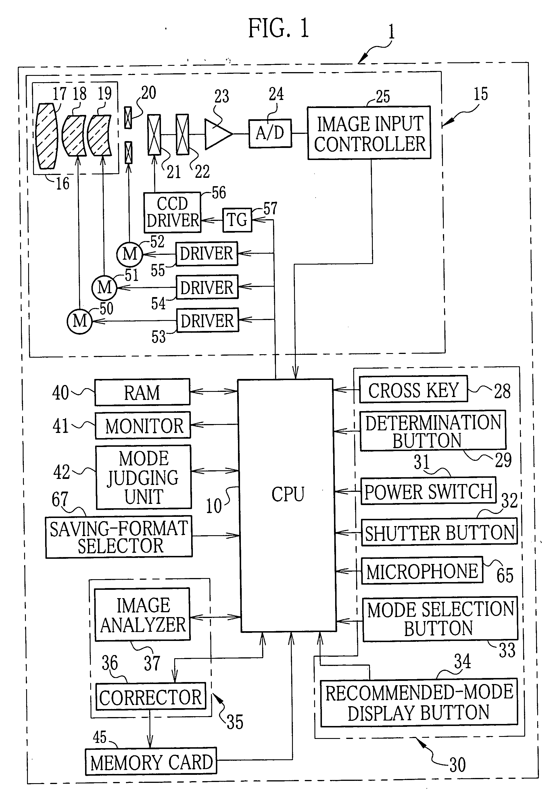
[0021]FIG. 1 is a block diagram showing an electrical structure of an electronic camera 1 according to the present invention. In the electronic camera 1, various circuits are integrally controlled by a CPU 10 connected to a camera unit 15, an operating unit 30, an image processor 35, a RAM 40, a monitor 41 and a mode judging unit 42.

[0022] The camera unit 15 comprises a taking lens 16, a stop mechanism 20, a CCD image sensor (imaging member) 21, a correlation double sampling circuit (CDS) 22, and an amplifier (AMP) 23, an A / D converter 24, an image input controller 25, a zoom-lens driving motor 50, a focus-lens driving motor 51, a stop driving motor 52, drivers 53, 54 and 55, a CCD driver 56, and a timing generator 57. The taking lens 16 comprises a fixed lens 17, a zoom lens 18 and a focus lens 19. The zoom lens 18 and the focus lens 19 are respectively moved by the zoom-lens driving motor 50 and the focus-lens driving motor 51. Meanwhile, the stop mechanism 20 is disposed in fron...


PUM


Abstract

Upon pressing a power switch, a power supply of an electronic camera is turned on. A subject image is taken by a camera unit and is converted into image data for which a corrector performs image processing. The processed image data is displayed on a monitor as a through image in real time. A function for displaying a recommended shooting mode is turned on, and a shooting angle is determined while the through image is viewed. Upon half depression of a shutter button, the through image is sent to an image analyzer to estimate a shooting scene. On the basis of the estimated shooting scene, a mode judging unit judges the shooting mode to be recommended. The monitor displays the recommended shooting mode. The displayed shooting mode is selected and determined to set the recommended shooting mode. Regular shooting is performed upon full depression of the shutter button.

Description

FIELD OF THE INVENTION [0001] The present invention relates to an imaging device capable of changing shooting modes having different shooting conditions, and further relates to a method for displaying a recommended shooting mode. BACKGROUND OF THE INVENTION [0002] Electronic cameras provided with shooting modes of different shooting conditions are widely used. In this kind of the electronic camera, shooting is adapted to be performed for various shooting scenes under the proper shooting conditions (see Japanese Patent Laid-Open Publication No. 2005-175684). It is possible to manually change the shooting mode by operating a mode selector disposed on a camera body, for example. The shooting modes include a person shooting mode, a scene shooting mode, a night-view shooting mode and so forth. Under the respective shooting modes, proper shooting conditions are set in accordance with a shooting scene. [0003] Besides the shooting modes corresponding to the shooting scenes, many electronic ...

Claims


Application Information

Patent Timeline
Patent Type & Authority Applications(United States)
IPC IPC(8): H04N5/222
CPCH04N5/23293H04N23/633
Inventor KATO, YOSUKE
Owner FUJIFILM CORP
Why Eureka
Try Eureka