Light emitting diode array, method of manufacturing the same, backlight assembly having the same, and LCD having the same

Inactive Publication Date: 2007-07-05
LG DISPLAY CO LTD
View PDF33 Cites 36 Cited by
  • Summary
  • Abstract
  • Description
  • Claims
  • Application Information

AI Technical Summary

Benefits of technology

[0019] An object of the present invention is to provide a light-emitting diode array, a method of fabricating the same, a backlight assembly having the

Problems solved by technology

However, since the CRT is bulky and heavy, it is inadequate for implementing a miniaturized and lightweight electronic product.
Also, since the LED is a semiconductor device, it has high reliability and a long lifespan.
In the process of mounting the LEDs 50, however, the LEDs 50 ma

Method used


Image

  • Light emitting diode array, method of manufacturing the same, backlight assembly having the same, and LCD having the same
  • Light emitting diode array, method of manufacturing the same, backlight assembly having the same, and LCD having the same
  • Light emitting diode array, method of manufacturing the same, backlight assembly having the same, and LCD having the same

Examples


Embodiment Construction

[0037] Reference will now be made in detail to the preferred embodiments of the present invention, examples of which are illustrated in the accompanying drawings. Wherever possible, the same reference numbers will be used throughout the drawings to refer to the same or like parts.

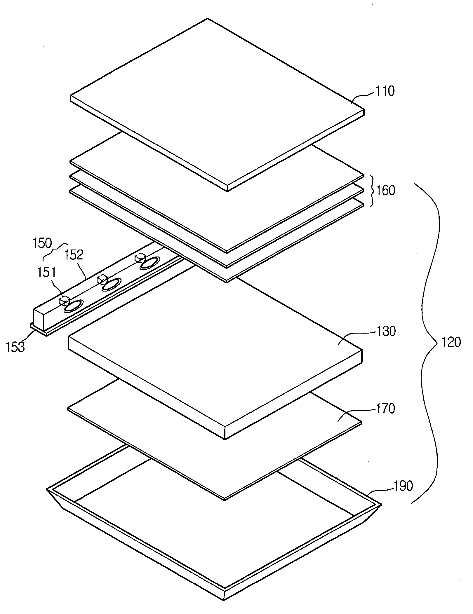
[0038]FIG. 2A is an exploded perspective view of an edge type LCD according to an embodiment of the present invention.

[0039] Referring to FIG. 2A, the edge type LCD of the present invention includes a liquid crystal panel 110 for displaying an image and a backlight assembly 120 for supplying light to the liquid crystal panel 110.

[0040] The backlight assembly 120 includes an LED array 150 disposed at a side thereof, a printed circuit board (PCB) 153 having a conductive pattern to supply an electric signal to the LED array 150, a light guide plate 130 for converting light emitted from the LED array 150 into surface light, optical sheets 160 disposed on the light guide plate 130 to diffuse and condense the ...


PUM


Abstract

Provided is a light emitting diode array including: a plurality of light emitting chips spaced apart from one another by a predetermined distance; and a fixing member that positions the plurality of light emitting chips at predetermined heights and/or predetermined directions. Also provided are methods for manufacturing the light emitting diode array, a backlight assembly including the light emitting diode array, and a liquid crystal display device including the light emitting diode array.

Description

BACKGROUND OF THE INVENTION [0001] The present invention claims the benefit of Korean Patent Application No. 10-2005-0133678, filed in Korea on Dec. 29, 2005, which is hereby incorporated by reference. FIELD OF THE INVENTION [0002] The present invention relates to a light emitting diode array with improved brightness uniformity, a method of fabricating the same, a backlight assembly having the same, and a liquid crystal display device (LCD) having the same. DESCRIPTION OF THE RELATED ART [0003] Cathode ray tubes (CRTs) have been widely used as monitors for televisions, measuring instruments, information terminals, and the like. However, since the CRT is bulky and heavy, it is inadequate for implementing a miniaturized and lightweight electronic product. [0004] To replace the CRT, a LCD using an electric field and optical effect, a plasma display panel (PDP) using a gas discharge, and an electro luminescence display (ELD) using a field emission effect have been developed. Among them,...

Claims


Application Information

Patent Timeline
IPC IPC(8): G02F1/1335
CPCG02B6/0068G02B6/0073G02B6/009G02F1/133603H01L25/0753H01L2224/49107H01L33/60H01L2224/48091H01L2224/48227H01L33/486H01L2924/00014G02F1/1335
Inventor JUNG, SUNG MIN
Owner LG DISPLAY CO LTD
Why Eureka
Try Eureka