Resonance chamber of mobile phone

a mobile phone and resonance chamber technology, applied in the direction of transducer details, electrical transducers, electrical apparatus, etc., can solve the problem of limited inner space available for loudspeakers in mobile phones

Inactive Publication Date: 2007-07-05
HON HAI PRECISION IND CO LTD
View PDF6 Cites 28 Cited by
  • Summary
  • Abstract
  • Description
  • Claims
  • Application Information

AI Technical Summary

Benefits of technology

[0007]According to a preferred embodiment of the present invention, a resonance chamber of a mobile phone includes a shell defining a resonance cavity for receiving a speaker therein. A plurality of holes are defined in the shell facing towards a first side of the speaker. A channel is defined in the shell extending laterally from a second side of the speaker oppos

Problems solved by technology

As design style for mobile phones emphasizes lightness, smallness, energy-efficiency, and low cost, the inner space available for loudspeakers within mobile phones is therefore limited.
There

Method used


Image

  • Resonance chamber of mobile phone
  • Resonance chamber of mobile phone
  • Resonance chamber of mobile phone

Examples


Embodiment Construction

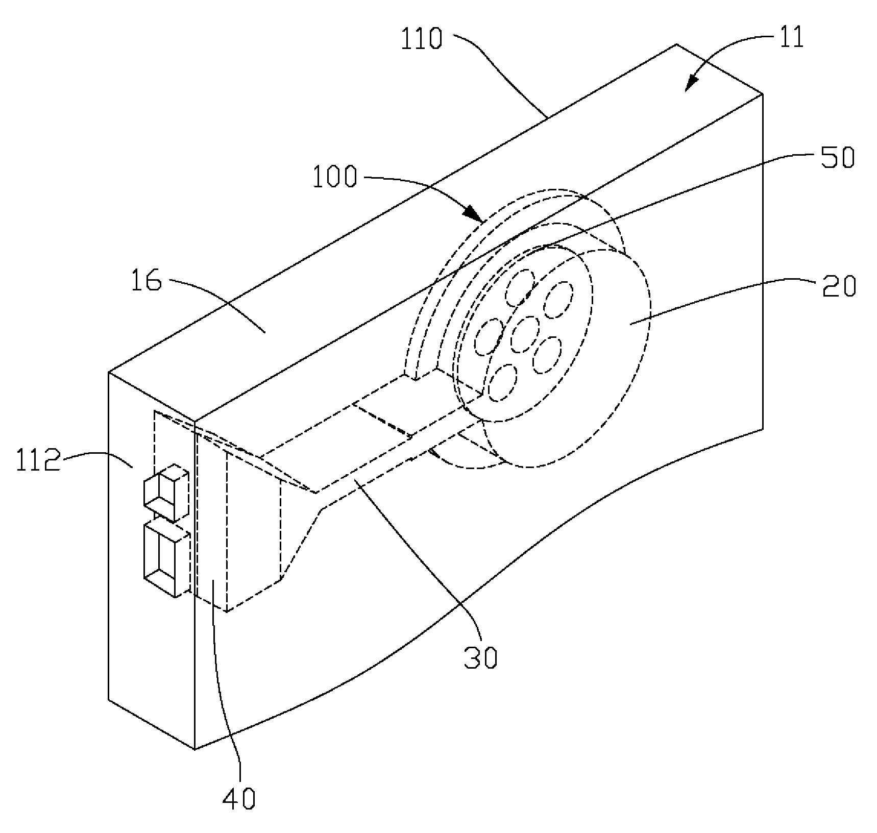
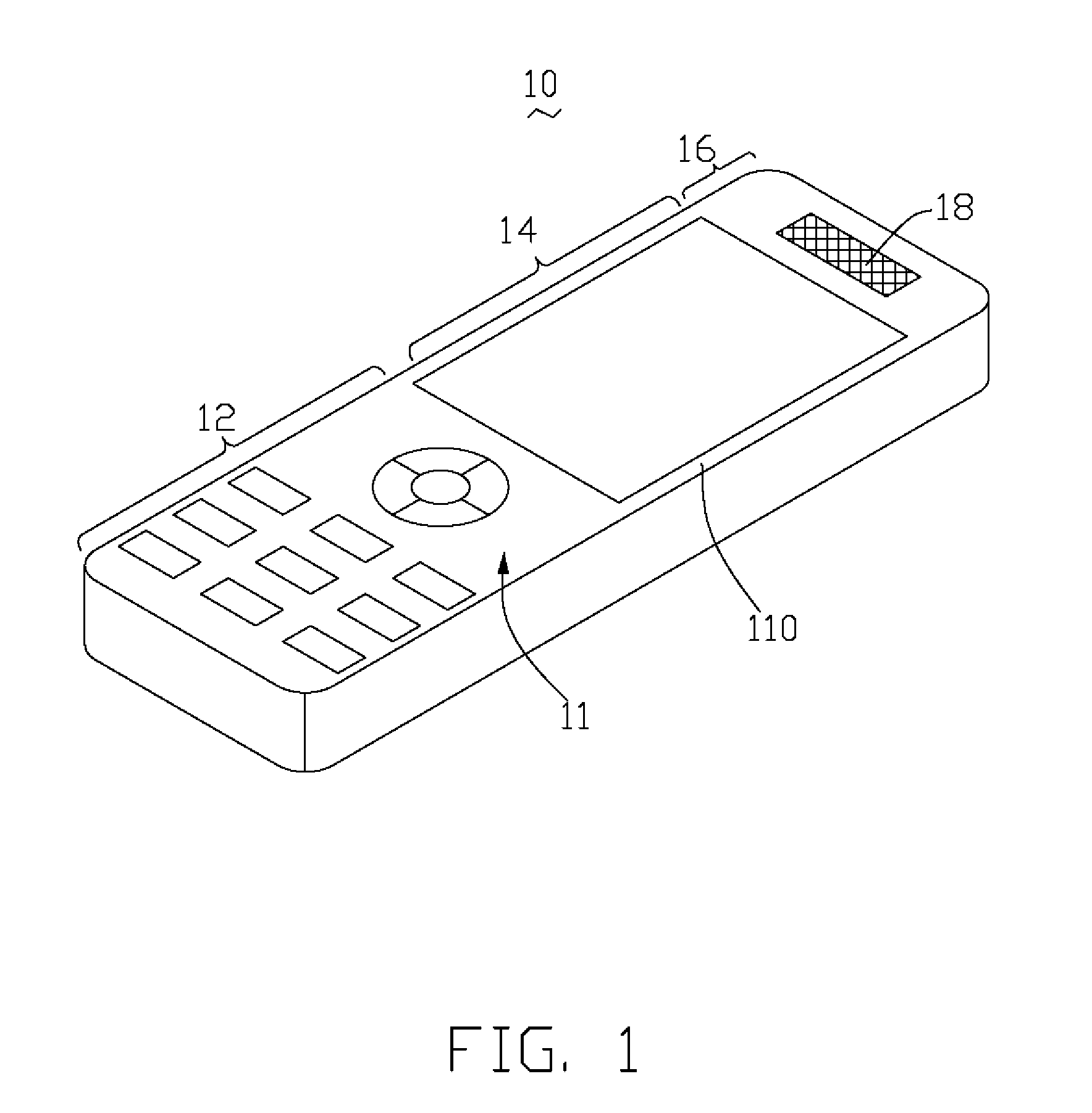
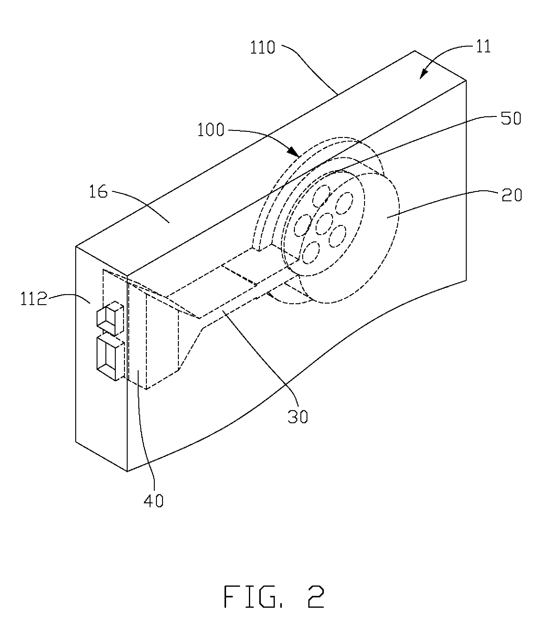
[0014]FIG. 1 shows an isometric view of a mobile phone 10 having a cuboid-shaped shell 11 defining an inner space therein for receiving components, such as PCB (printed circuit board), antenna, battery, and so on. The shell 111 includes an output section 16, a display section 14, and an input section 12. The input section 12 has a plurality of keys (not labeled) or a touch panel (not shown) for inputting signals arranged on a front side 110 of the shell 11. The output section 16 of the mobile phone 10 receives a speaker 50 (FIG. 2) which can transform electric signals into mechanical vibrations so as to transmit acoustic messages therein. The speaker 50 has a magnetic circuit in which a magnetic field generated by a magnet passes through a base member, a magnetic core having coil wound thereon, and a diaphragm. A plurality of holes 18 are defined in the front side 110 of the output section 16 of the shell 111 positioned corresponding to the section of the front side 110 closest to t...


PUM


Abstract

A resonance chamber of mobile phone includes a shell (11) defining a resonance cavity (20) for receiving a speaker (50) therein. A plurality of holes (18) is defined in the shell facing to a first side of the speaker. A channel (30) is defined in the shell extending laterally from a second side opposite to the first side of the speaker and communicating with the resonance cavity. An opening (40) is defined in the shell to communicate the channel with the environment. The channel has a width and a length smaller than a wavelength of an acoustic wave generated by the speaker.

Description

BACKGROUND OF THE INVENTION[0001]1. Field of the Invention[0002]The present invention relates generally to a resonance chamber of a mobile phone, and more particularly to a resonance chamber with improved resonance in low frequency voices.[0003]2. Description of Related Art[0004]Sound is the most important means by which people communicate with each other, and so creating new methods for sound transference allows greater communication between people. Electroacoustic transducers are key components in transferring sound. A typical electroacoustic transducer has a magnetic circuit in which a magnetic field generated by a magnet passes through a base member, a magnetic core and a diaphragm and returns to the magnet again. When an oscillating electric current is supplied to a coil wound around the magnetic core, the corresponding oscillating magnetic field generated by the coil is then superimposed onto the static field of the magnetic circuit. The resulting oscillation generated in the ...

Claims


Application Information

Patent Timeline
IPC IPC(8): H04R1/02
CPCH04R1/2842H04M1/035
Inventor YANG, TSUNG-LUNG
Owner HON HAI PRECISION IND CO LTD
Why Eureka
Try Eureka