
Coaxial cable connector with clamping insert

a technology of coaxial cable and insert, which is applied in the direction of coupling device connection, two-part coupling device, electrical apparatus, etc., can solve the problems of excessive rf leakage of connector, reduced signal strength, and increased contact resistance, so as to improve the pull strength

Active Publication Date: 2007-07-05
CORNING GILBERT INC
View PDF20 Cites 112 Cited by
  • Summary
  • Abstract
  • Description
  • Claims
  • Application Information

AI Technical Summary

Benefits of technology

[0021]In some embodiments, the post further comprises a raised portion. The jacket and / or braided shield can be sandwiched between the front end of the insert and the raised portion of the post in the forward position, for example in order to improve pull strength.

Problems solved by technology

It is known in the art that the passage of moisture between the coaxial cable jacket and the surrounding F-connector can lead to corrosion, increased contact resistance, reduced signal strength, and excessive RF leakage from the connector.
However, such connectors can not be installed quickly, as by a simple crimp or compression tool, but instead mating threads of such connector must be tightened, as by using a pair of wrenches.

Method used


Image

  • Coaxial cable connector with clamping insert
  • Coaxial cable connector with clamping insert
  • Coaxial cable connector with clamping insert

Examples


Embodiment Construction

[0042]Reference will now be made in detail to the present preferred embodiment(s) of the invention, examples of which are illustrated in the accompanying drawings. Whenever possible, the same reference numerals will be used throughout the drawings to refer to the same or like parts.

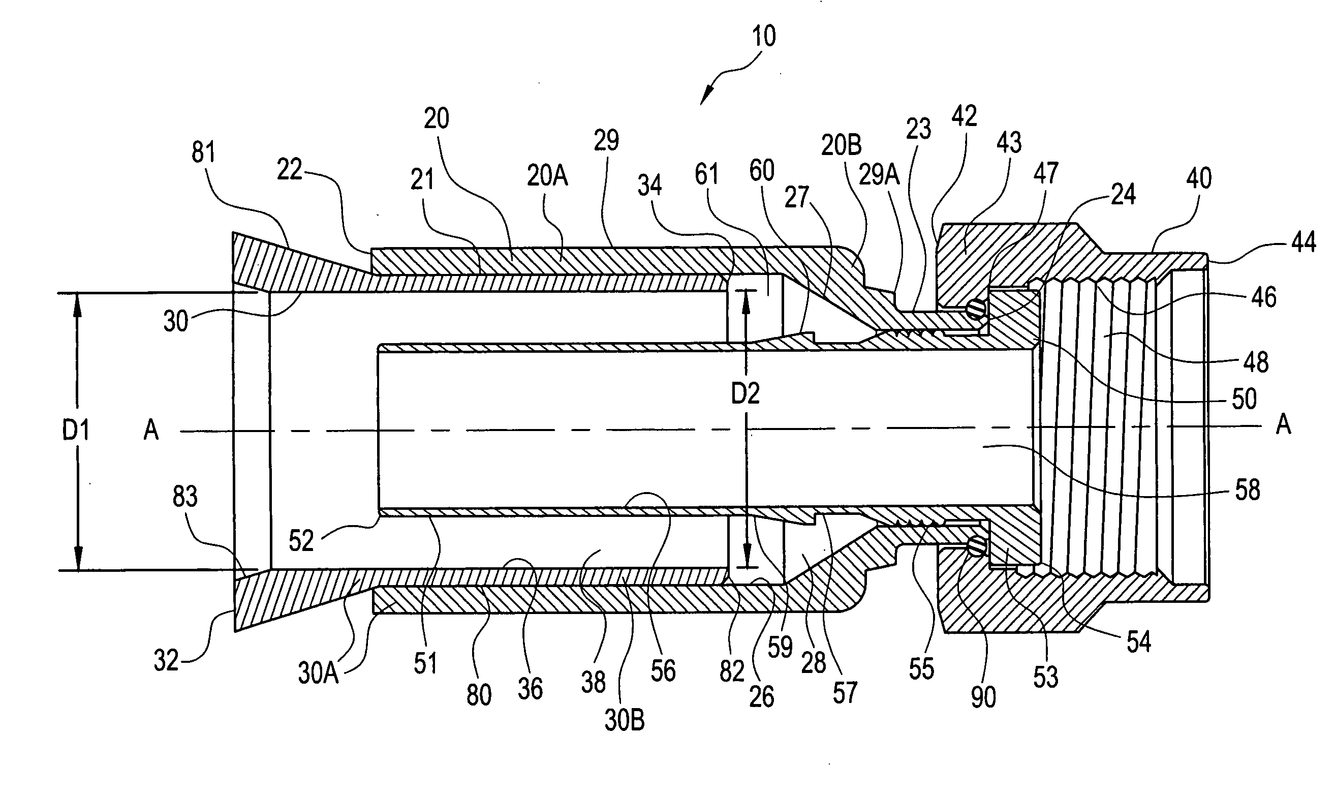
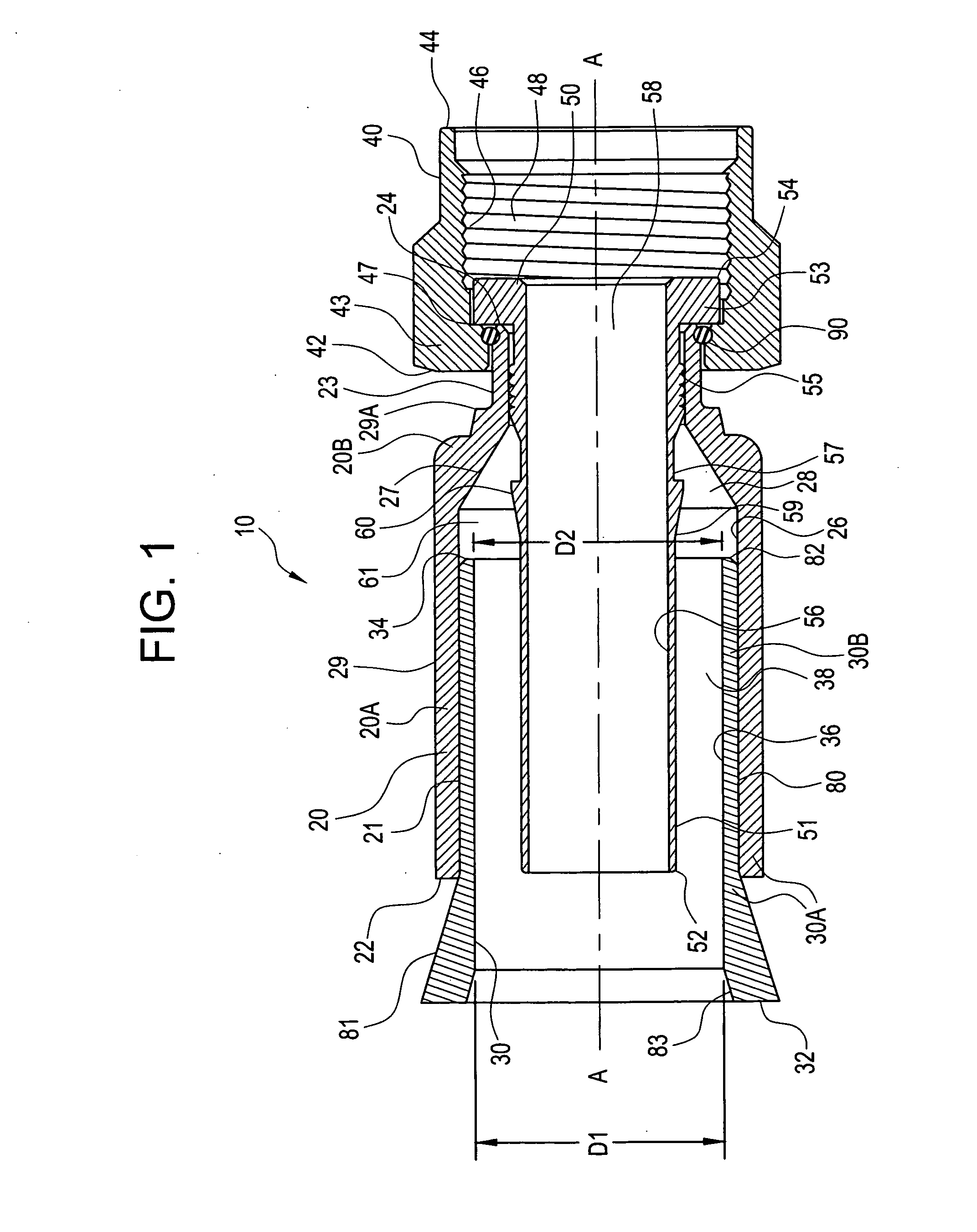
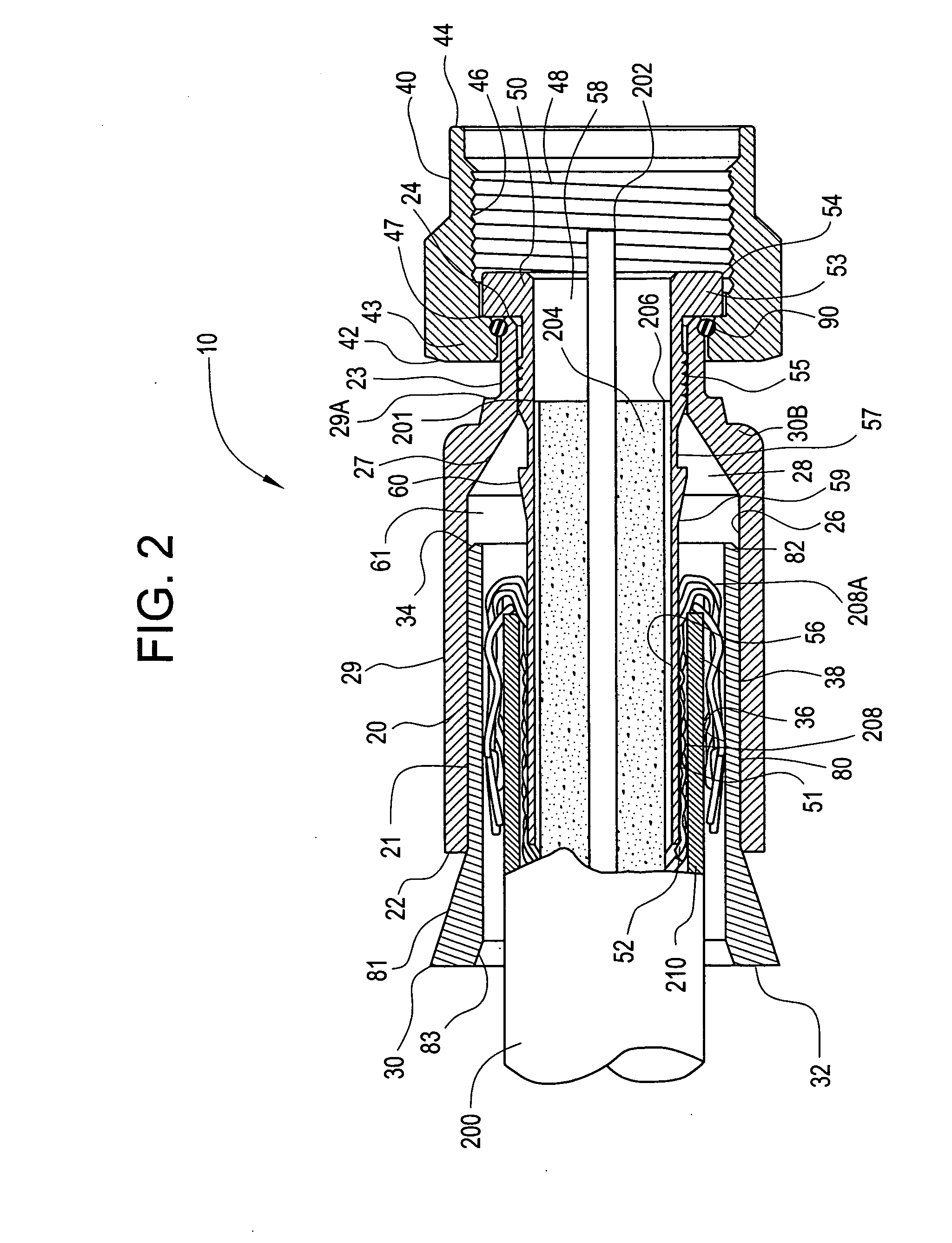
[0043]FIG. 1 schematically illustrates a first embodiment of a connector as disclosed herein, comprising a clamping insert in a rearward position. FIG. 8 schematically illustrates a second embodiment of a connector as disclosed herein, comprising a clamping insert in a rearward position. FIG. 10 schematically illustrates a third embodiment of a connector as disclosed herein, comprising a clamping insert in a rearward position. FIG. 2 schematically illustrates a coaxial cable partially inserted into the connector of FIG. 1, or, alternatively, the connector partially inserted onto the cable. FIG. 3 schematically illustrates the connector of FIG. 1 with a coaxial cable fully inserted into the connector or, a...


PUM


Abstract

A connector for coaxial cable is disclosed herein that has an outer body and a clamp insert. The clamp insert is mounted at the rear of the body and accepts an end of a coaxial cable. Both the front and rear ends of the insert are deformed radially inwardly when the body and the insert and compressed so as to grip the coaxial cable and form a seal. A related method for connecting the coaxial cable and connector is also disclosed.

Description

[0001]This application claims the benefit of priority under 35 U.S.C. § 119(e) of U.S. Provisional Application Ser. No. 60 / 755,262 filed on Dec. 29, 2005.BACKGROUND OF THE INVENTION[0002]1. Field of the Invention[0003]The present invention relates generally to coaxial cable connectors.[0004]2. Technical Background[0005]Coaxial cable connectors such as F-connectors are used to attach a coaxial cable to another object such as an appliance or device or junction having a terminal adapted to engage the connector. Coaxial cable F-connectors are often used to terminate a drop cable in a cable television system. The coaxial cable typically includes a center conductor surrounded by a dielectric, in turn surrounded by a conductive grounding foil and / or braided shield, hereinafter collectively referred to as the outer conductor; the outer conductor is in turn surrounded by a protective outer jacket. The F-connector is secured over a prepared end of a jacketed coaxial cable, allowing the end of...

Claims


Application Information

Patent Timeline
IPC IPC(8): H01R9/05
CPCH01R4/5016H01R9/0518H01R9/0524H01R2103/00H01R13/5205H01R13/622H01R24/40H01R13/025
Inventor BURRIS, DONALD ANDREWLUTZ, WILLIAM BERNARD
Owner CORNING GILBERT INC
Features
  • Generate Ideas
  • Intellectual Property
  • Life Sciences
  • Materials
  • Tech Scout
  • Unparalleled Data Quality
  • Higher Quality Content
  • 60% Fewer Hallucinations
Learn More