
Davenport® multi-spindle screw machine, and improved tool arm for use therein

a multi-spindle screw machine and screw arm technology, which is applied in the direction of mechanical equipment, bearing unit rigid support, manufacturing tools, etc., can solve the problems of less aggressive relative speed and feed between the tool and the workpiece, unnecessary tool chatter, and shorten the service interval in the most demanding of machining applications. , to achieve the effect of reducing tool chatter, tightening part tolerances, and increasing tool li

Active Publication Date: 2007-07-05
BRINKMAN PROD INC
View PDF7 Cites 0 Cited by
  • Summary
  • Abstract
  • Description
  • Claims
  • Application Information

AI Technical Summary

Benefits of technology

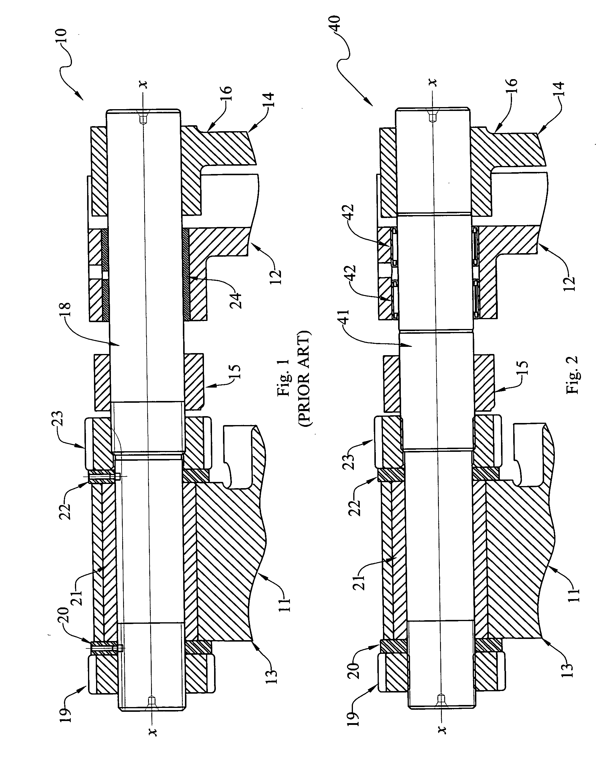
[0014] Still another object is to provide a tighter-fitting rotative connection between a tool arm (14) and a revolving head cap (13) of a Davenport® multi-spindle automatic screw machine that affords the advantages and capabilities of reduced tool chatter, increased tool life, tighter part tolerances, more aggressive relative speeds and feeds between the tool and a workpiece, and substantially-extended service intervals in the most demanding applications. In some cases, the service interval may be extended by about fifty times the service interval associated with prior art bronze bushing embodiments.

Problems solved by technology

While this prior art arrangement has worked well for many years, it is now realized that the increases in the radial spacing between bushing 24 and shaft 18, such as caused by wear, has contributed to unnecessary tool chatter, decreased tool life, looser part tolerances, less-aggressive relative speeds and feeds between the tool and the work-piece, and shortened service intervals in the most demanding of machining applications.
Experience has found that these pins are unnecessary.

Method used


Image

  • Davenport® multi-spindle screw machine, and improved tool arm for use therein
  • Davenport® multi-spindle screw machine, and improved tool arm for use therein
  • Davenport® multi-spindle screw machine, and improved tool arm for use therein

Examples


Embodiment Construction

[0021] At the outset, it should be clearly understood that like reference numerals are intended to identify the same structural elements, portions or surfaces consistently throughout the several drawing figures, as such elements, portions or surfaces may be further described or explained by the entire written specification, of which this detailed description is an integral part. Unless otherwise indicated, the drawings are intended to be read (e.g., cross-hatching, arrangement of parts, proportion, degree, etc.) together with the specification, and are to be considered a portion of the entire written description of this invention. As used in the following description, the terms “horizontal”, “vertical”, “left”, “right”, “up” and “down”, as well as adjectival and adverbial derivatives thereof (e.g., “horizontally”, “rightwardly”, “upwardly”, etc.), simply refer to the orientation of the illustrated structure as the particular drawing figure faces the reader. Similarly, the terms “inw...


PUM

PropertyMeasurementUnit
diameteraaaaaaaaaa
diametersaaaaaaaaaa
timeaaaaaaaaaa

Abstract

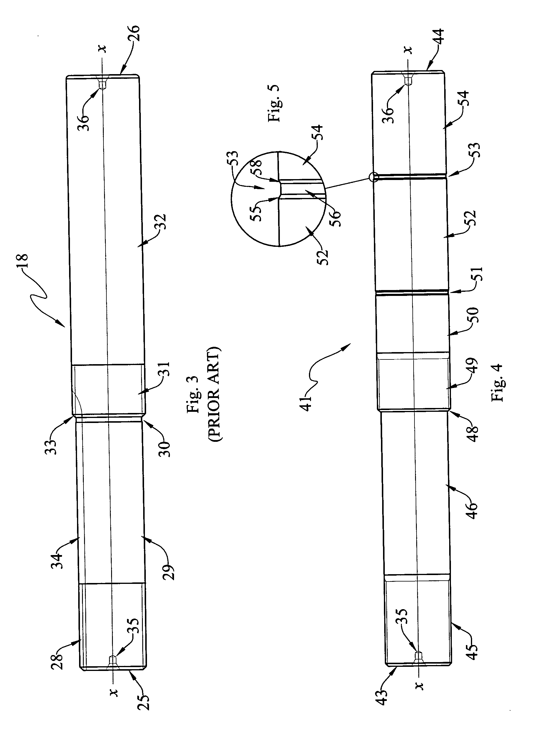
An improved Davenport® multi-spindle automatic screw machine has a tool arm (14) mounted on a shaft (41) for rotational movement relative to a revolving head cap (13). A needle bearing (42, 42) is operatively arranged between the shaft and the revolving head cap. The bearing is radially loaded as said bearing is installed and that the individual needles of same remain elastically deformed by the radial load immediately after said bearing has been installed. The shaft has a hardened surface (52) that is engaged by the needles. The diameter of the shaft hardened surface portion is greater than the diameters of the adjacent shaft portions. Annular recesses (51, 53) extend into the shaft at either end of the hardened portion. These recesses have frusto-conical surfaces (55) that act as ramps to guide insertion of the press-fittable needle bearing into the space between the shaft and the head cap.

Description

TECHNICAL FIELD [0001] The present invention relates generally to Davenport® multiple-spindle automatic screw machines, and, more particularly, to an improved mechanism by which a tool arm may be rotatably and tightly mounted on a revolving head cap of a Davenport® screw machine so as to afford the capabilities of reduced tool chatter, increased tool life, tighter part tolerances, more-aggressive relative speeds and feeds between the tool and a work-piece, and substantially-extended service intervals in the most demanding machining applications. BACKGROUND ART [0002] A screw machine is a machine tool in which a tool is moved to engage a rotating workpiece. [0003] A Davenport® multiple-spindle automatic screw machine (available from Davenport Machine, Inc., 167 Ames Street, Rochester, N.Y. 14611) typically has five workpiece-holding spindles that are rotatably indexable from station to station. At each station, a tool is adapted to be selectively moved to engage a rotating workpiece ...

Claims


Application Information

Patent Timeline
Patent Type & Authority Applications(United States)
IPC IPC(8): B23Q3/155F16F15/121
CPCB23B9/005F16C3/02F16C19/48F16C25/08Y10T82/20F16C35/12Y10T483/17Y10T82/2562F16C27/04
Inventor BELPANNO, SANDRO G.KRUSE, ROBERT C.
Owner BRINKMAN PROD INC
Learn More