Cache coherency control method, chipset, and multi-processor system

a coherency control and cache technology, applied in the field of multi-processor systems, chipsets, and cache coherency control methods, can solve the problems of ccnuma can more hardly demonstrate the performance than, the difference between the time to access memory in one node, and the performance of improving performance, so as to improve the memory access latency

Inactive Publication Date: 2007-07-05
HITACHI LTD
View PDF2 Cites 47 Cited by
  • Summary
  • Abstract
  • Description
  • Claims
  • Application Information

AI Technical Summary

Benefits of technology

[0017]The effect of the invention can be demonstrated quantitatively. Let us suppose a system that requires 100 ns for a snoop process in the local node, 130 ns for a memory data response in the local node, 160 ns for a snoop process in the remote node, and 190 ns for a memory data response in the remote node. When the invention is not used, the memory access latency for the local node is 160 ns. When the invention is used, the memory access latency for the local node is 130 ns when hit. When data is hit, the invention can improve the memory access latency for the local node by 30 ns, i.e., less than 20%.
can be demonstrated quantitatively. Let us suppose a system that requires 100 ns for a snoop process in the local node, 130 ns for a memory data response in the local node, 160 ns for a snoop process in the remote node, and 190 ns for a memory data response in the remote node. When the invention is not used, the memory access latency for the local node is 160 ns. When the invention is used, the memory access latency for the local node is 130 ns when hit. When data is hit, the invention can improve the memory access latency for the local node by 30 ns, i.e., less than 20%.

Problems solved by technology

When all CPUs are connected to the same memory unit or processor bus, a memory interface or the processor bus bottlenecks to prevent the performance from improving.
Such construction often causes a difference between the time to access memory in one node and the time to access memory in a remote node.
Conventionally, it has been reported that ccNUMA can more hardly demonstrate the performance than UMA because the ccNUMA causes a large access difference between the local memory and the remote memory.
On the other hand, the multi-processor system composed of multiple nodes is subject to a serious problem of cache coherency control between processors.
There is a possibility of causing unnecessary traffic.
In short, the broadcast-based snoop protocol may cause unnecessary traffic because a snoop request is always broadcast, but a fast response is available when the remote node caches data.

Method used


Image

  • Cache coherency control method, chipset, and multi-processor system
  • Cache coherency control method, chipset, and multi-processor system
  • Cache coherency control method, chipset, and multi-processor system

Examples


embodiment 1

[0043]Overview

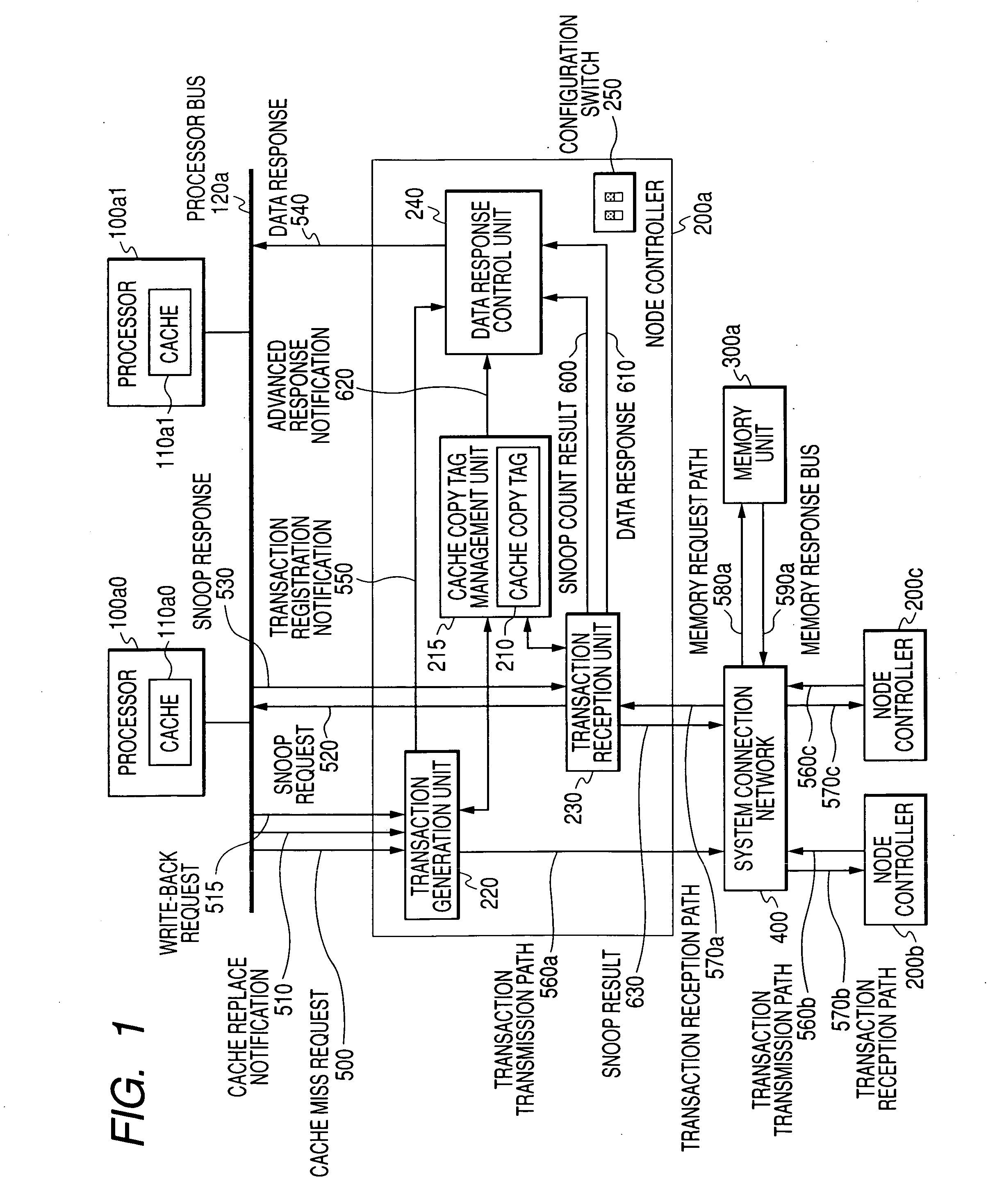
[0044]FIG. 1 is a schematic diagram showing a multi-processor system composed of a node controller having a cache coherency control function as embodiment 1 of the invention.

[0045]One or more node controllers 200 and memory units 300 are connected to each other via a system connection network 400. The memory unit 300 may be provided in the same node as the node controller 200 or on a system board. That is, a node controller 200a and a memory unit 300a construct a node. A node controller 200b and a memory unit 300b construct another node. Though not shown explicitly in FIG. 1, the memory unit 300 is composed of a memory controller and a main storage. Though not shown in FIG. 1, an I / O unit is connected via the node controller 200 or the system connection network 400. Multiple I / O devices are connected to the I / O unit. The node controller 200 connects with one or more processors 100 via the processor bus 120. The processor 100 includes a cache 110. While the embodiment u...

modification 1

of Embodiment 1

[0087]The cache miss request according to modification 1 operates similarly to embodiment 1. On the other hand, the cache replacement process according to modification 1 operates slightly differently from embodiment 1. That is, the cache copy tag management unit 215 is notified of the cache replacement from the transaction generation unit 220. At this time, the cache copy tag management unit 215 is also notified of a node that includes memory having an address targeted for the cache replacement. When the targeted address points to a remote node, the process updates the cache copy tag similarly to embodiment 1 as mentioned above. When the targeted address points to the local node, the process does not update the cache copy tag. Modification 1 of embodiment 1 has now been described.

[0088]FIG. 19 shows a flowchart of the cache replacement process according to modification 1. This flowchart can replace the flowchart in FIG. 18. When a cache replacement request occurs, the...

modification 2

of Embodiment 1

[0090]The construction of modification 2 is mostly common to that of embodiment 1, i.e., as shown in FIG. 1. According to modification 2, however, the configuration switch 250 of the node controller 200 includes a cache replacement cache replacement cache replacement control switch 270. The cache replacement cache replacement cache replacement control switch 270 enables or disables the replacement.

[0091]The cache copy tag management unit 215 is notified of cache replacement from the transaction generation unit 220 and then checks the state of the cache replacement cache replacement control switch 270. When the cache replacement cache replacement control switch 270 enables the replacement, the cache copy tag management unit 215 updates the cache copy tag similarly to the basic example of embodiment 1. When the cache replacement cache replacement control switch 270 disable the replacement, the cache copy tag management unit 215 does not update the cache copy tag.

[0092]F...


PUM


Abstract

In a multi-processor system, counting snoop results bottlenecks the broadcast-based snoop protocol. The directory-based protocol delays the latency when remote node caches data. There is a need for shortening the memory access latency using a snoop and cache copy tag information. When the local node's cache copy tag information is available, the memory access latency can be shortened by omitting a process to count snoop results. When memory position information is used to update the cache copy tag during cache replacement, it is possible to increase a ratio to hit a copy tag during reaccess from the local node.

Description

CLAIM OF PRIORITY[0001]The present application claims priority from Japanese patent application JP 2006-000028 filed on Jan. 4, 2006, the content of which is hereby incorporated by reference into this application.FIELD OF THE INVENTION[0002]The present invention relates to a multi-processor system, a chipset, and a cache coherency control method and more particularly to a technology for shortening the memory access latency.BACKGROUND OF THE INVENTION[0003]In recent years, computer capabilities have improved and requirements for computers are accordingly increasing. Such tendency leads to widespread use of a multi-processor system mounted with multiple processors especially in the field of servers. When all CPUs are connected to the same memory unit or processor bus, a memory interface or the processor bus bottlenecks to prevent the performance from improving. For a middle to large scale multi-processor system that uses more than four CPUs, it is a frequent practice to arrange multip...

Claims


Application Information

Patent Timeline
Patent Type & Authority Applications(United States)
IPC IPC(8): G06F13/28
CPCG06F12/0813G06F12/0831G06F12/0822
Inventor UEHARA, KEITAROOKITSU, JUNMURAKAMI, YOSHIKI
Owner HITACHI LTD
Why Eureka
Try Eureka