Tilt-rotor aircraft

a tilt-rotor aircraft and tilt-rotor technology, applied in the direction of rotor aircraft, vertical landing/take-off aircraft, power plant arrangement/mounting, etc., can solve the problems of economic cost of acquisition and operation, the difficulty of manoeuvre, landing or taking off of twin-prop airplanes that lose all thrust from one side, and the yaw problem can escalate into irrecoverable roll

Active Publication Date: 2007-07-12
BURRAGE ROBERT GRAHAM
View PDF12 Cites 122 Cited by
  • Summary
  • Abstract
  • Description
  • Claims
  • Application Information

AI Technical Summary

Problems solved by technology

The V-22 eventually entered low-rate initial production in 1999, but subsequently was grounded after two crashes in 2000; revised flight tests began in May 2002 and it is now in limited production.
The reasons for the relative success (or lack of it) of these three concepts lie in the economic cost of acquisition and operation.
But the helicopter is VTOL capable, whereas the fixed wing design is not.
Secondly, comparing a twin tilt-rotor design with the above two designs: The twin tilt-rotor can be both CTOL and VTOL capable, the other two designs cannot.
For example a twin-prop airplane that loses all thrust from one side becomes more difficult to manoeuvre or land or take off at low speed, where yaw problems can escalate into irrecoverable roll.
Wing mounted twin tilt-rotor designs typically guard against this problem of asymmetric loss of power by the use of complex cross-wing transmissions between their engines, however this cannot compensate for major asymmetry of airflow from the rotor on one wing to the other.
Such problems occur when one rotor enters or leaves the vortex ring state before the other, and when in ground effect the flow symmetry is destroyed by proximity to other aircraft disturbing the air or by physical discontinuities of the effective ground surface.

Method used


Image

  • Tilt-rotor aircraft
  • Tilt-rotor aircraft
  • Tilt-rotor aircraft

Examples


Embodiment Construction

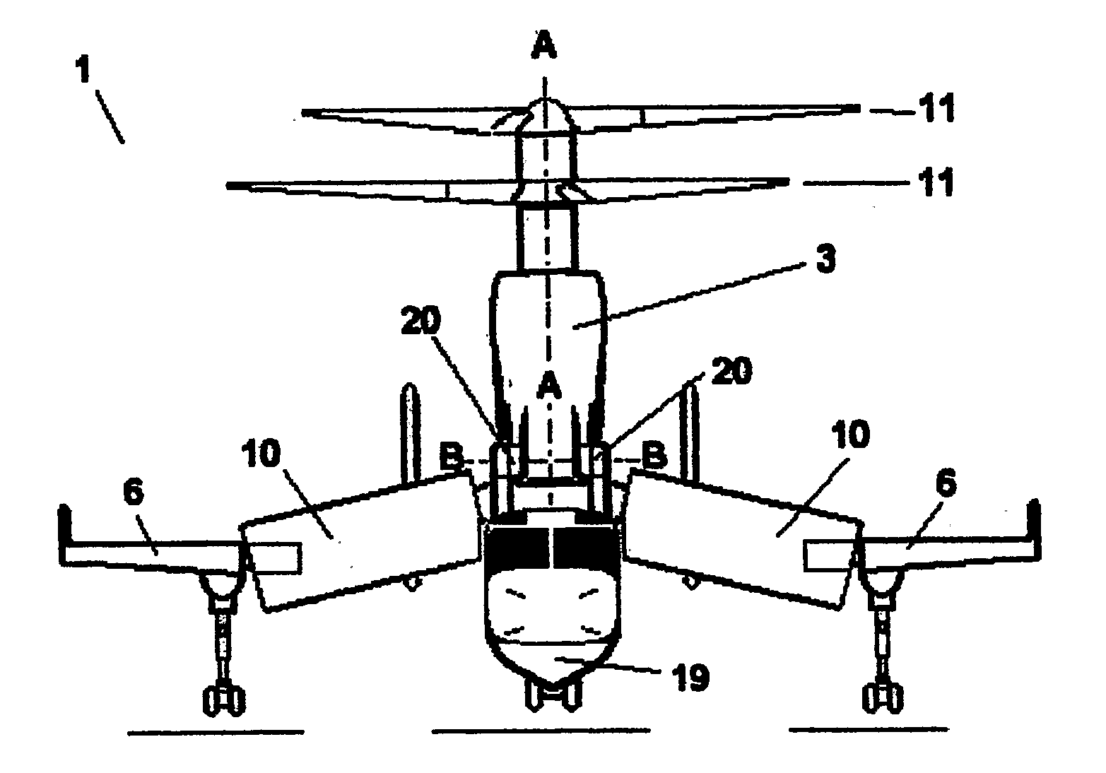
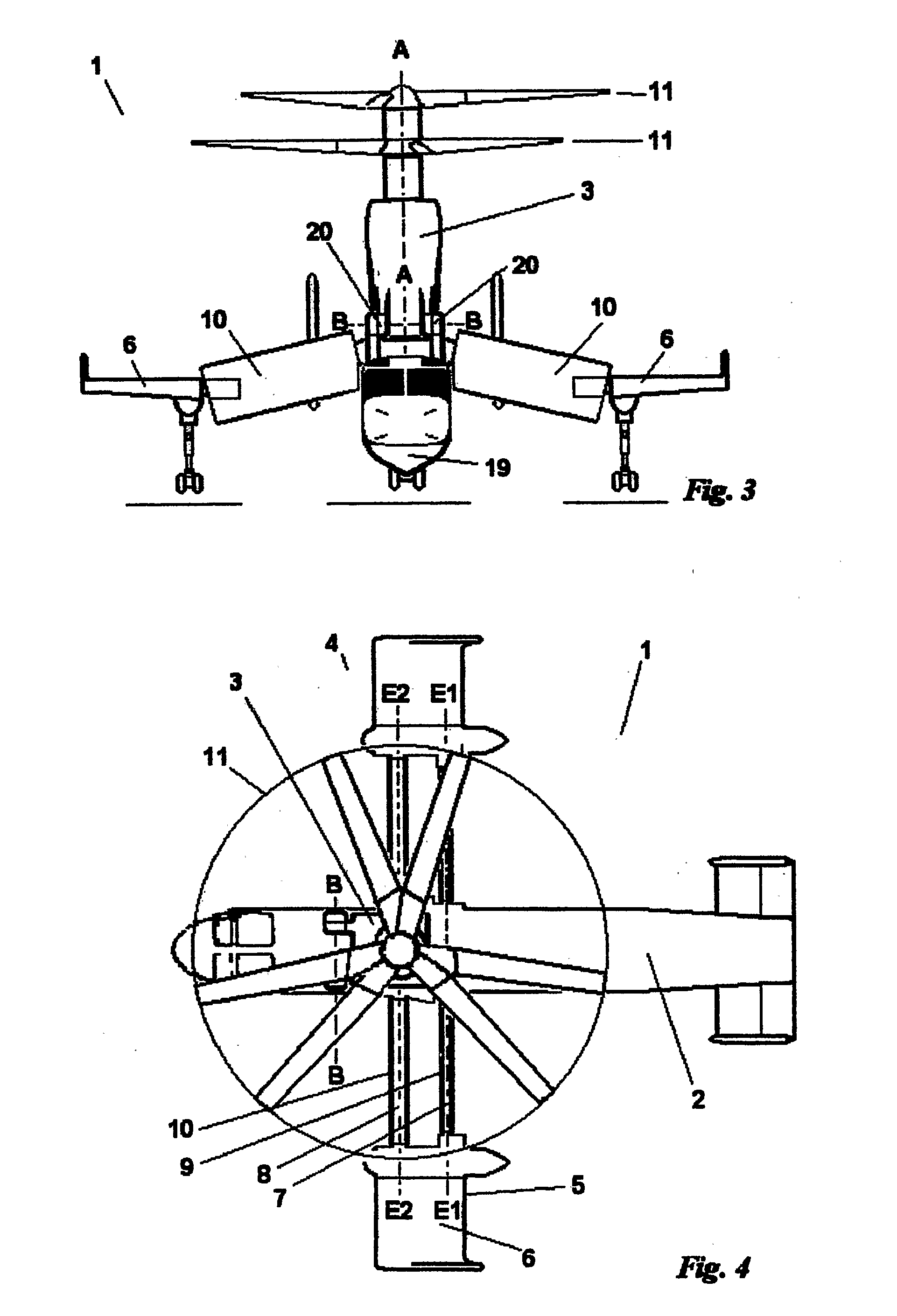
[0072] With reference to FIGS. 1 to 4, a convertiplane 1 comprises a fuselage 2, a rotornacelle 3 attached above the fuselage 2, and a wing 4.

[0073] The rotornacelle 3 supports two rotors 11 that rotate in opposite directions about the common axis A, so setting aside other influences, the force vector produced by the rotors 11 is aligned to axis A. The rotornacelle 3 houses the engines and known devices—not forming part of the present invention and therefore not shown—for transmitting power to and for controlling the cyclic and collective pitch of the rotors 11. In particular the rotors are coupled through a differential gear to equalise the torque supplied to each, any imbalance relative to axis A manifesting itself as a torque reaction on the differential casing which is transmitted to the airframe. This torque imbalance is cancelled by control of the relative collective pitch of the two rotors, and this also is employed to maintain yaw control of the aircraft in hover mode and a...


PUM


Abstract

A tilt-rotor aircraft (1) comprising a pair of contra-rotating co-axial tiltable rotors (11) on the longitudinal centre line of the aircraft. The rotors (11) may be tiltable sequentially and independently. They may be moveable between a lift position and a flight position in front of or behind the fuselage (19).

Description

BACKGROUND OF THE INVENTION [0001] As is known, there are many designs of aircraft, herein referred to as convertiplanes, seeking to combine the advantages of fixed-wing propeller aircraft and of helicopters, for example by use of tilt-rotors or by tilt-wings. Of these, arguably only the twin tilt-rotor designs are close to full production. [0002] Twin tilt-rotor designs have a long history. In 1934, U.S. Pat. No. 1,951,817 was granted to Blount for his “airplane-helicopter”. In 1958 the Bell XV-3 became the first tilt-rotor to convert to the aeroplane mode; a 15-year test programme proved that it could fly safely and smoothly throughout its flight envelope. The XV-3 was limited in speed by its use of blades designed for helicopter flight, and this was remedied in Bell's next project, the XV-15, by use of high twist blades. The first XV-15 was rolled out in 1976, and by 1986 the two prototypes had achieved an unofficial record for rotorcraft of 301 knots, had accumulated 530 flight ...

Claims


Application Information

Patent Timeline
Patent Type & Authority Applications(United States)
IPC IPC(8): B64C27/22B64C29/00B64C39/04
CPCB64C39/04B64C29/0033
Inventor BURRAGE, ROBERT GRAHAM
Owner BURRAGE ROBERT GRAHAM
Why Eureka
Try Eureka