Traction band with improved ground-engaging lugs

a lug and lug technology, applied in the direction of driving belts, belts/chains/gearrings, mechanical instruments, etc., can solve the problems of less efficiency, more costly lugs, and in the end, less lugs, and improve the resistance and rigidity of lugs. , the effect of less tendency to bend

Inactive Publication Date: 2007-07-12
SOUCY INT
View PDF21 Cites 23 Cited by
  • Summary
  • Abstract
  • Description
  • Claims
  • Application Information

AI Technical Summary

Benefits of technology

[0019] When the lugs are in use, their base (the portion of the lug which is contact with the traction band) is subjected to extreme traction and compression forces. Overtime, the prior art lugs will break or at least be partially destroyed. By longitudinally displacing lug material away from the general center of the lug, where the forces are the lowest, to the outer edges, where the traction and compression forces are the highest, the resistance and rigidity of the lug are greatly improved without adding new material. Since each lug is m

Problems solved by technology

The net results were indeed stronger lugs but also a heavier tra

Method used


Image

  • Traction band with improved ground-engaging lugs
  • Traction band with improved ground-engaging lugs
  • Traction band with improved ground-engaging lugs

Examples


Embodiment Construction

[0029] With reference to the annexed drawings, the preferred embodiments of the present invention will be herein described for indicative purposes and by no means as of limitation.

[0030] The following description will be made with respect to a traction band for a snowmobile. However, it is to be understood that traction bands used on other track-laying vehicles shall comprise characteristics which can differ from the one set forth here. Still, the ground-engaging lugs of the present invention can be used on other types of traction bands without departing from the scope of the invention which will be defined in the appended claims.

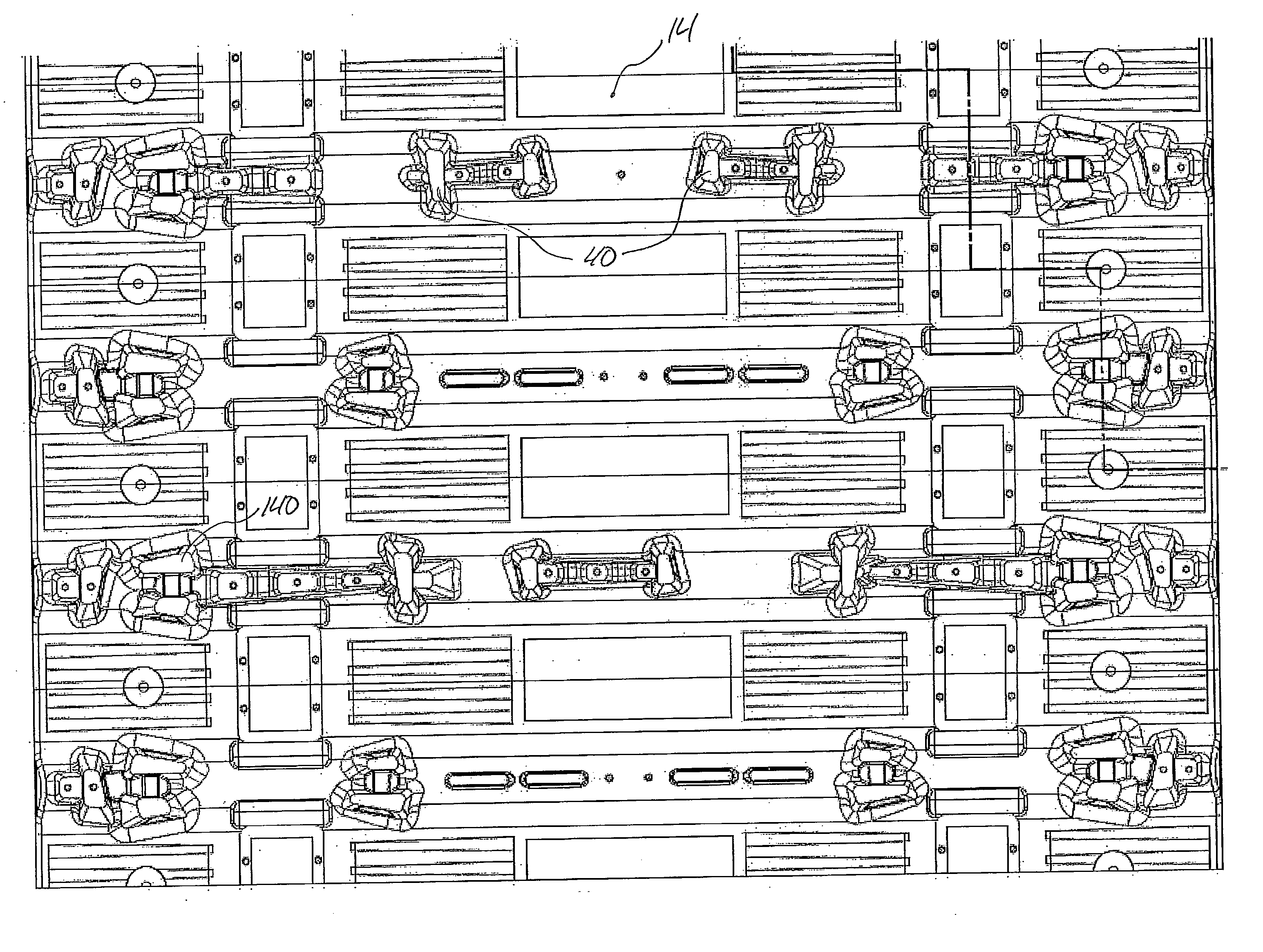
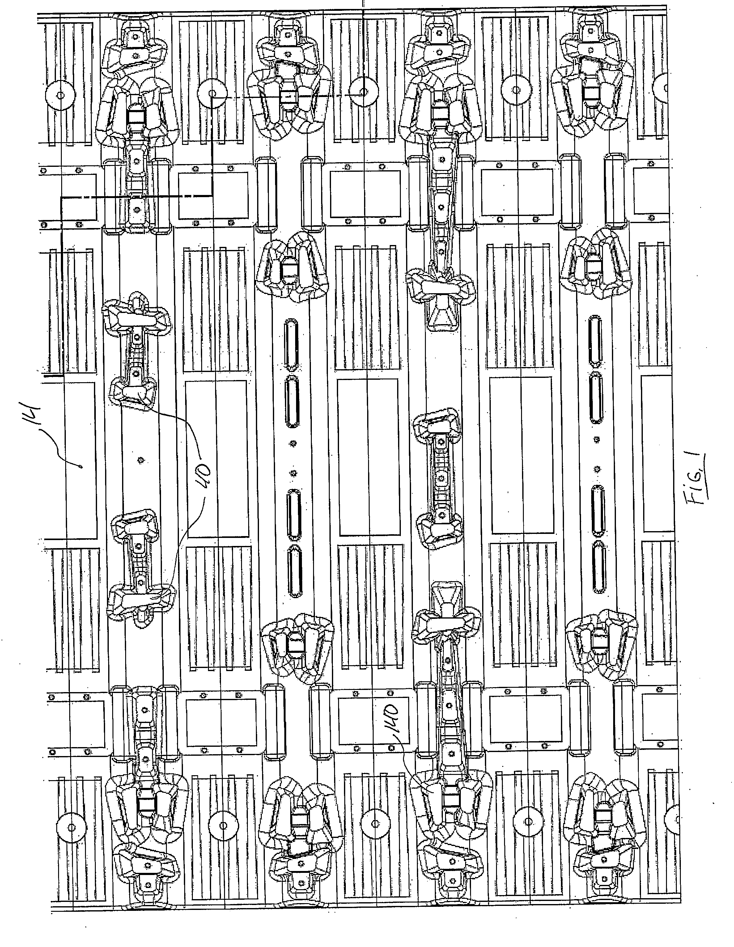
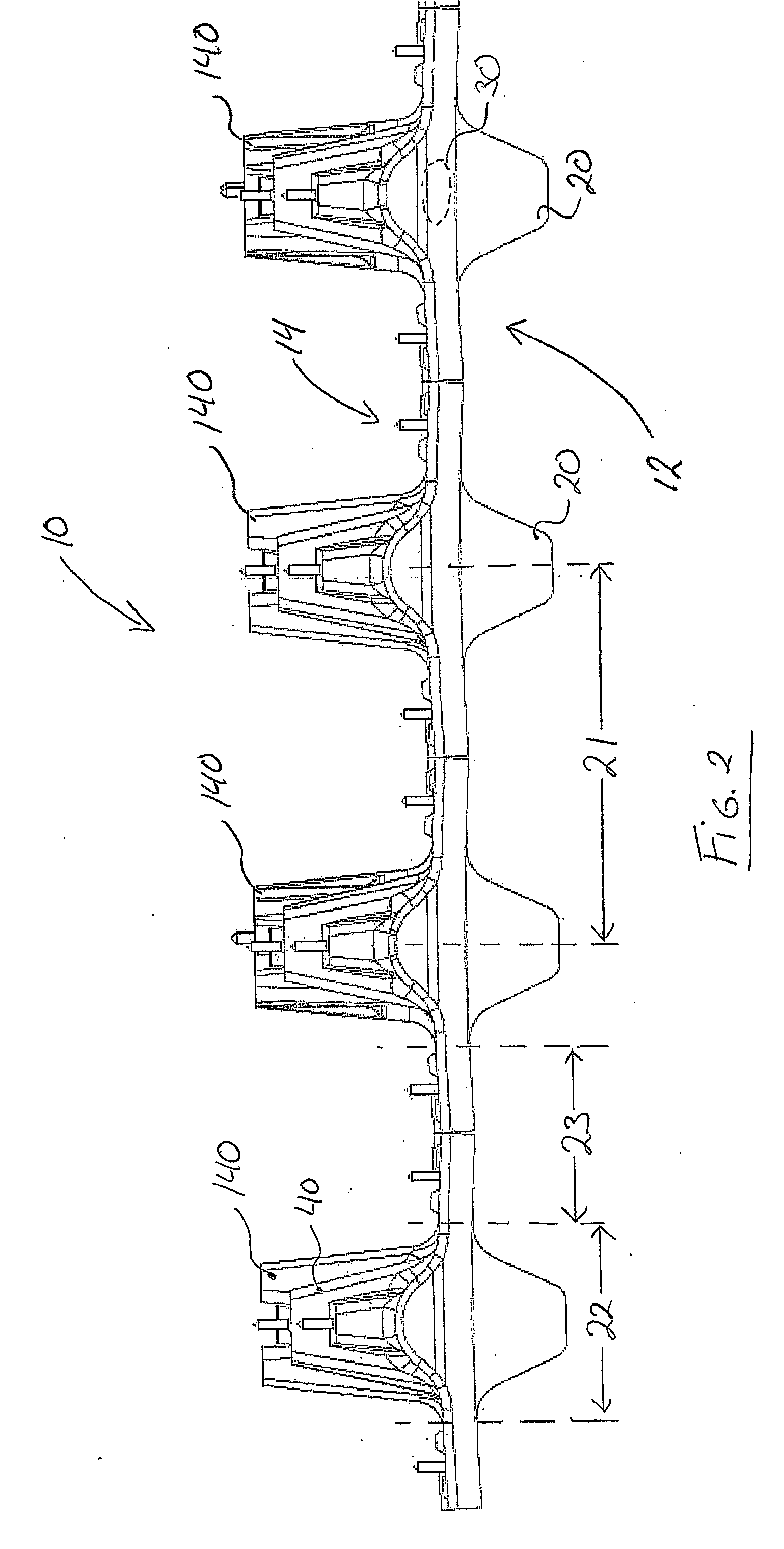
[0031] Referring now to FIGS. 1 and 2, we can see partial top and side views of a traction band 10 which comprises a sprocket engaging surface 12 and a ground-engaging surface 14. The sprocket engaging surface 12 preferably comprises rows of drive lugs 20 which are adapted to cooperate with the sprocket wheel (not shown) of the vehicle in order to transmi...


PUM


Abstract

A traction band with improved ground-engaging lugs is disclosed. The traction band generally comprises an endless body extending along the longitudinal axis of the traction band. The body comprises an outer ground-engaging surface and an inner sprocket wheel engaging surface. The inner sprocket wheel engaging surface can comprise rows of drive lugs cooperating with the sprocket wheel. The outer ground-engaging surface comprises a series ground-engaging lugs which, according to the present invention, have a generally H-shape, I-shape, C-shape, O-shape or a rectangular shape when viewed from the top.

Description

FIELD OF THE INVENTION [0001] The present invention relates to an endless traction band or track that is used to propel track laying vehicles. More particularly, the present invention relates to a traction band with improved ground-engaging lugs. BACKGROUND OF THE INVENTION [0002] Traction band for use on snowmobile, wheel-replacement traction kit, skid-steer and other well known track laying equipments and vehicles are known in the art and their uses increase with each passing year. The use of these traction bands allow track-laying vehicles to travel over soft, muddy, snowy, sandy and other similar terrain. [0003] In the case of traction bands for snowmobile, numerous improvements have been done throughout the years to enhanced the performance, the resistance, the rigidity, the noise profile and other characteristics of these bands. [0004] Nowadays, traction bands, especially for snowmobiles, are known to comprise transverse reinforcing rods or stiffeners to rigidify the band, spe...

Claims


Application Information

Patent Timeline
IPC IPC(8): B62D55/00
CPCB62D55/26B62D55/244
Inventor ST-AMANT, PASCAL
Owner SOUCY INT
Why Eureka
Try Eureka