
Organic el component

a technology of organic el and components, applied in the direction of discharge tube luminescnet screens, natural mineral layered products, transportation and packaging, etc., can solve the problems of increasing and achieve the effect of enhancing luminous efficiency and minimizing the attenuation of luminous efficiency and luminan

Inactive Publication Date: 2007-07-12
ROHM CO LTD
View PDF3 Cites 5 Cited by
  • Summary
  • Abstract
  • Description
  • Claims
  • Application Information

AI Technical Summary

Benefits of technology

[0011]In order to overcome the problems described above, preferred embodiments of the present invention provide an organic EL element capable of enhancing the luminous efficiency and minimizing the attenuation of the luminous efficiency and luminance.
[0012]In accordance with a first preferred embodiment of the present invention, an organic EL element includes a light emitting portion including a plurality of light emitting layers made of a light emitting material, and a plurality of charge transport layers made of a charge transport material capable of smoothly moving either positive or negative charges, wherein the plurality of light emitting layers and charge transport layers are alternately laminated.
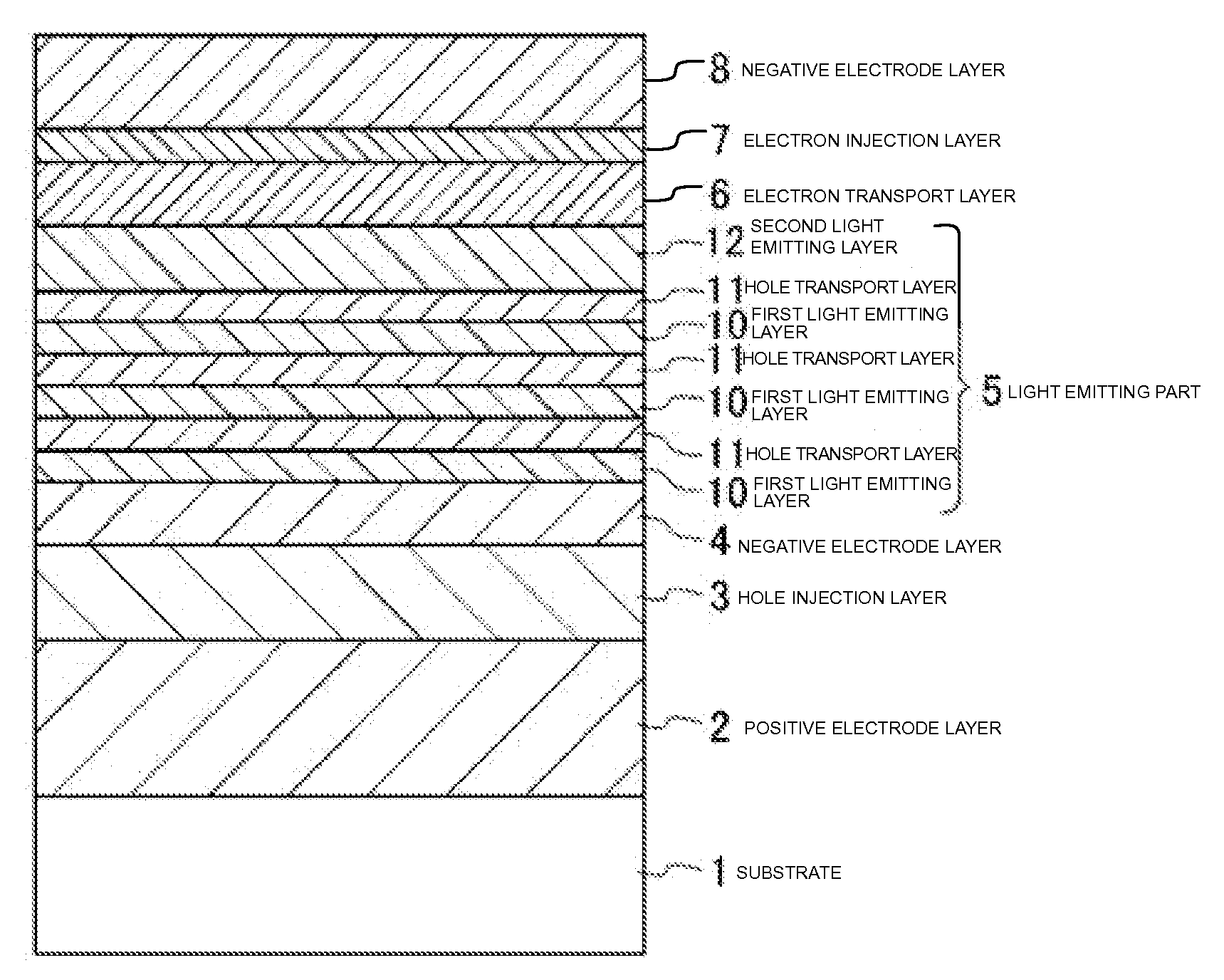
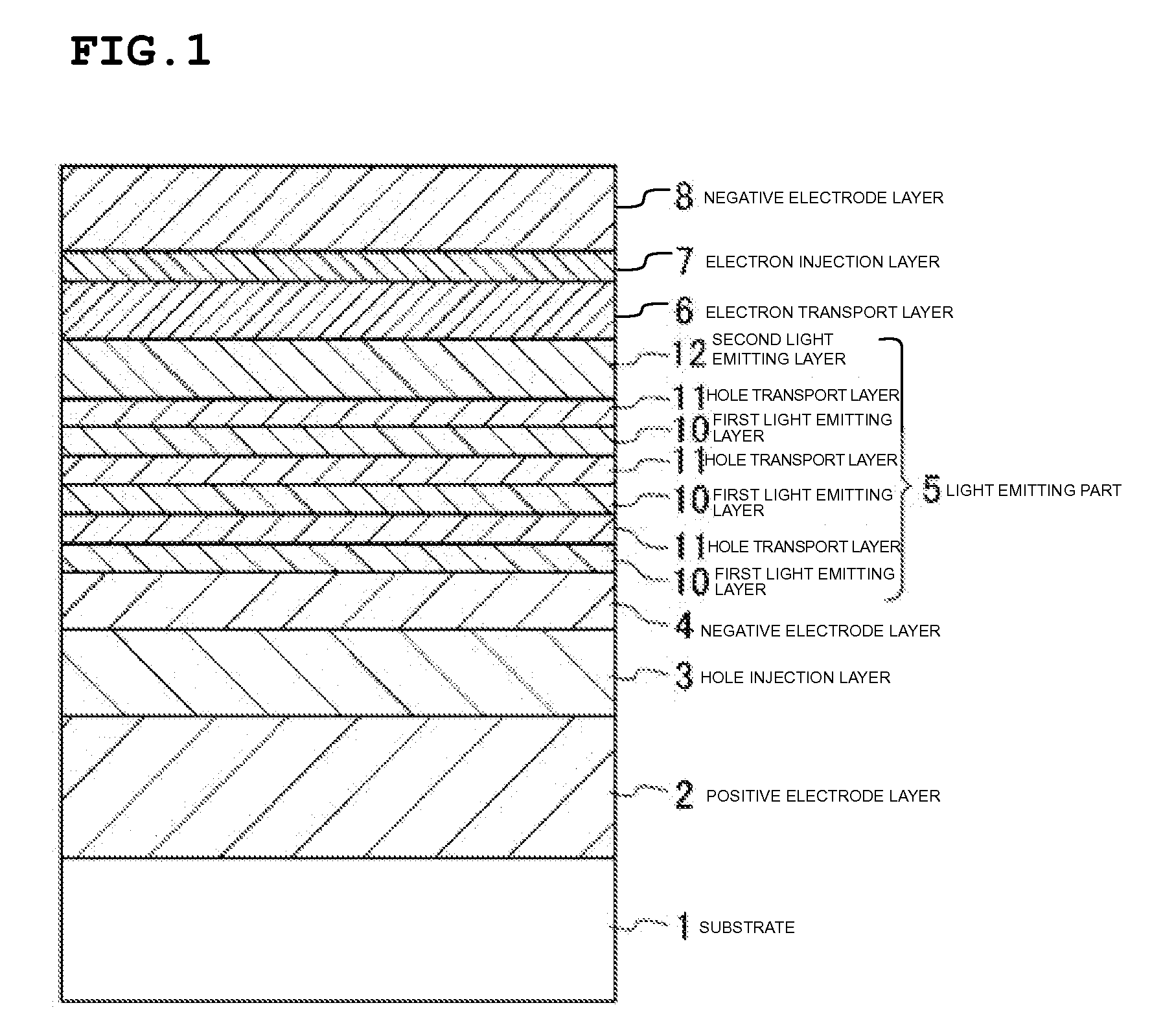
[0016]The light emitting portion has a laminated structure in which the plurality of light emitting layers and the plurality of charge transport layers are alternately laminated, and can recombine the holes and the electrons at each of the interfaces between the light emitting layers and the charge transport layers. Thereby, the area in which the holes and the electrons can be recombined can be increased as compared with the case where the light emitting layer is composed of a single layer. Therefore, the luminous efficiency can be enhanced.
[0017]The area in which the luminous elements are deactivated can be dispersed by increasing the interface to disperse the area in which the holes and the electrons are recombined. Therefore, the attenuation of the luminous efficiency and luminance can be minimized as compared with the organic EL element having a single light emitting layer in which the deactivation of the luminous element is concentrated.

Problems solved by technology

As a result, although luminous elements existing in the light emitting layer are not deactivated, the deactivation of the luminous elements at the interfaces of the light emitting layer unfortunately causes an increase in the attenuation of the luminous efficiency and luminance.

Method used


Image

  • Organic el component
  • Organic el component
  • Organic el component

Examples


Embodiment Construction

[0023]Hereinafter, preferred embodiments of the present invention will be described with reference to the drawings. FIG. 1 shows a sectional structure of an organic EL element according to a preferred embodiment of the present invention.

[0024]As shown in FIG. 1, in the organic EL element, a positive electrode layer 2, a hole injection layer 3, a hole transport layer 4, alight emitting portion 5, an electron transport layer 6, an electron injection layer 7, and a negative electrode layer 8 are laminated on a substrate 1.

[0025]The light emitting portion 5 has three first light emitting layers 10, three hole transport layers 11, and a second light emitting layer 12. The three first light emitting layers 10 and the three hole transport layers 11 are alternately laminated.

[0026]Since this organic EL element is configured to emit light from the side of the substrate 1, a transparent substrate transmitting light such as a glass substrate is used for the substrate 1. Similarly, the positive...


PUM

PropertyMeasurementUnit
thicknessaaaaaaaaaa
thicknessaaaaaaaaaa
thicknessaaaaaaaaaa

Abstract

An organic EL element includes a positive electrode layer, a hole injection layer, a hole transport layer, a light emitting portion, an electron transport layer, an electron injection layer, and a negative electrode layer laminated on a substrate. The light emitting portion has three first light emitting layers, three hole transport layers, and a second light emitting layer. The three first light emitting layers and the three layer hole transport layers are alternately laminated. The organic EL element is capable of enhancing luminous efficiency and minimizing the attenuation of the luminous efficiency and luminance.

Description

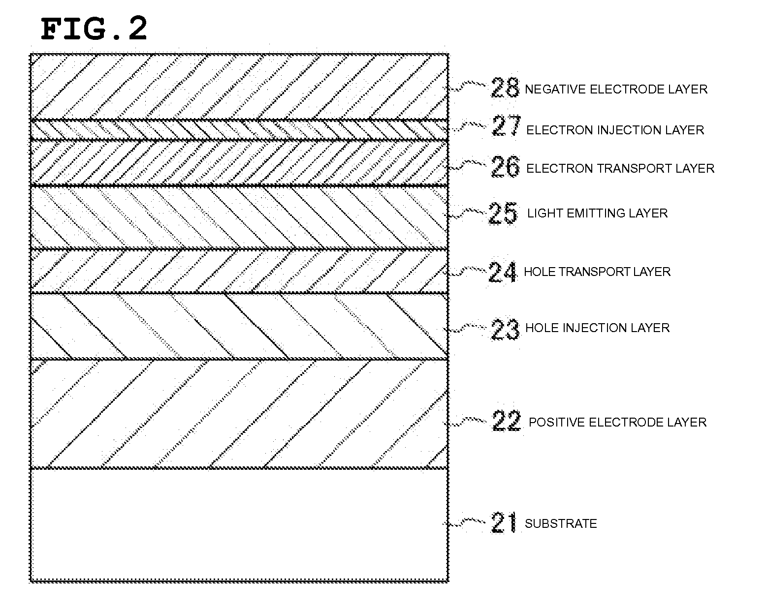
BACKGROUND OF THE INVENTION[0001]1. Field of the Invention[0002]The present invention relates to an organic EL element having a light emitting portion.[0003]2. Description of the Related Art[0004]An organic EL (electroluminescence) element has a substrate, a positive electrode layer, a hole transport layer, a light emitting layer (light emitting portion) for emitting light, and an electron transport layer or the like. This light emitting layer has been conventionally composed of a single light emitting layer made of a light emitting material such as Alq3 (trisaluminum) which is a combined body of organic matter and metal.[0005]Holes are injected into the single light emitting layer through the hole transport layer or the like from the positive electrode layer, and electrons are injected through the electron transport layer or the like from the negative electrode layer. The holes and electrons injected into the light emitting layer and confined therein are recombined to emit light in...

Claims


Application Information

Patent Timeline
Patent Type & Authority Applications(United States)
IPC IPC(8): H01L51/52H01L51/54
CPCH01L51/5036Y10T428/24942H01L51/5048H10K50/125H10K50/14
Inventor SAKAMOTO, GOSUKE
Owner ROHM CO LTD
Learn More