Electric shock protection device and portable electronic device including the same

a protection device and electronic device technology, applied in the direction of fixed capacitor details, feed-through capacitors, instruments, etc., can solve the problems of ac power leakage, dc power may not be sufficiently blocked, circuit unit damage, etc., to minimize the attenuation of communication signals

Active Publication Date: 2017-07-11
AMOTECH
View PDF11 Cites 1 Cited by
  • Summary
  • Abstract
  • Description
  • Claims
  • Application Information

AI Technical Summary

Benefits of technology

[0013]An object of the present invention is to provide an electric shock protection device for protecting an internal circuit and / or a user from leakage current due to static electricity or external power and minimizing the attenuation of communication signal to deliver it and a portable electronic device including the same.

Problems solved by technology

Especially, as a metal housing and a circuit unit forms a loop, when static electricity of a momentarily high voltage flows through a conductor such as a metal housing with a large external exposure area, this may damage a circuit unit such as IC and therefore, measures against this may be required.
However, if Y-CAP does not have a regular characteristic such as a non-genuine charger, DC power may not be sufficiently block by Y-CAP and furthermore, leakage current may occur by AC power.
Additionally, such leakage current may be spread along the ground part of circuit.
Since such leakage current can be delivered to a human body contactable conductor such as an external case of a portable electronic device, this may provide discomfort painful feeling to a user and in severe cases, a user may get fatal injuries due to electric shock.
However, as mentioned above, if a capacitance of a corresponding device is increased to effectively deliver communication signals, dielectric breakdown may be caused by external static electricity and accordingly, a corresponding device may be damaged.
Furthermore, as mentioned above, the implementation of a high breakdown voltage for blocking leakage current by external power and the implementation of a high-capacity capacitance for delivering communication signals may not be achieved due to their opposite effects.

Method used


Image

  • Electric shock protection device and portable electronic device including the same
  • Electric shock protection device and portable electronic device including the same
  • Electric shock protection device and portable electronic device including the same

Examples


Embodiment Construction

[0068]Preferred embodiments of the present invention will be described below in more detail with reference to the accompanying drawings. The present invention may, however, be embodied in different forms and should not be constructed as limited to the embodiments set forth herein. Parts not relating to description are omitted in the drawings in order to clearly describe the present invention and like reference numerals refer to like elements throughout.

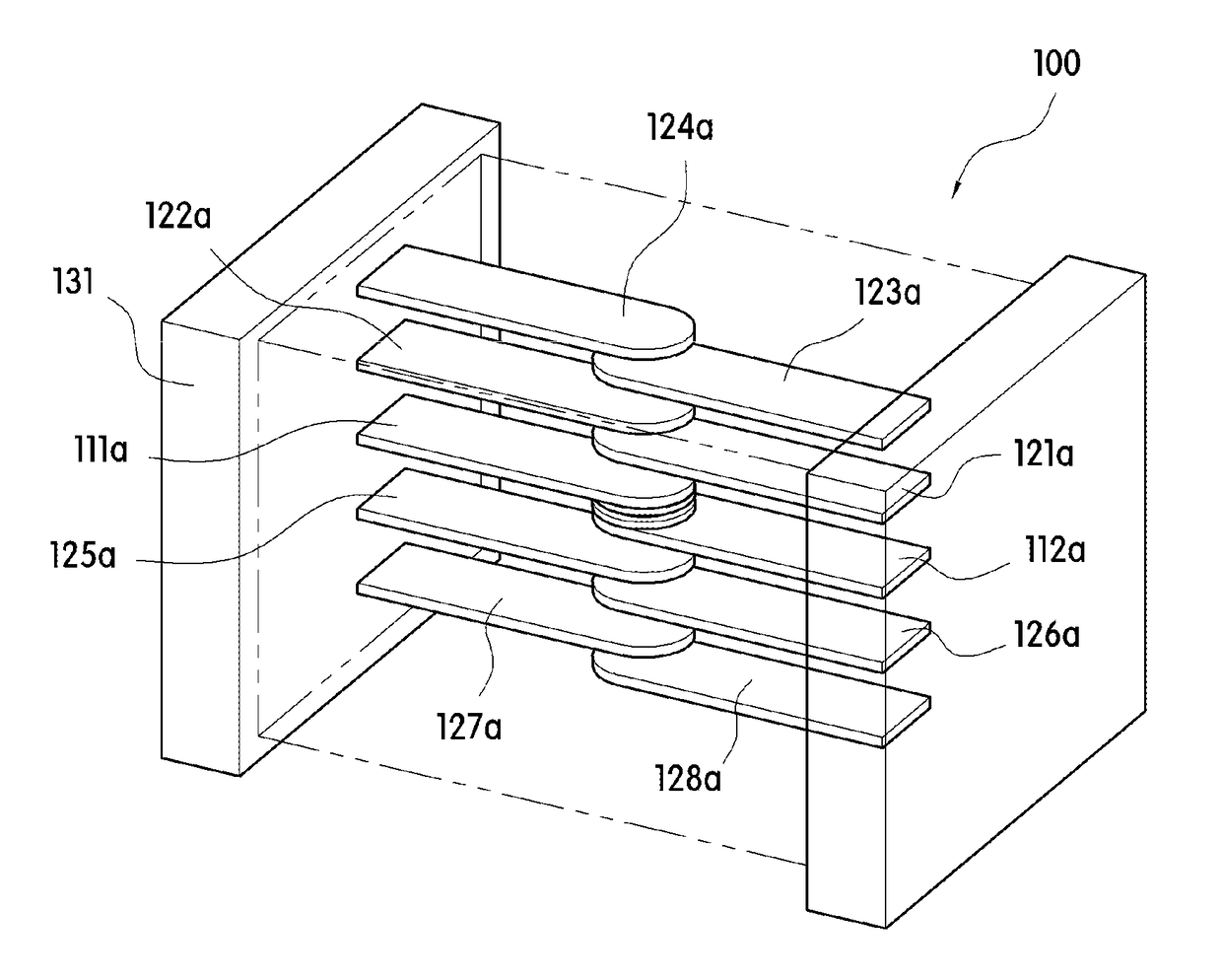
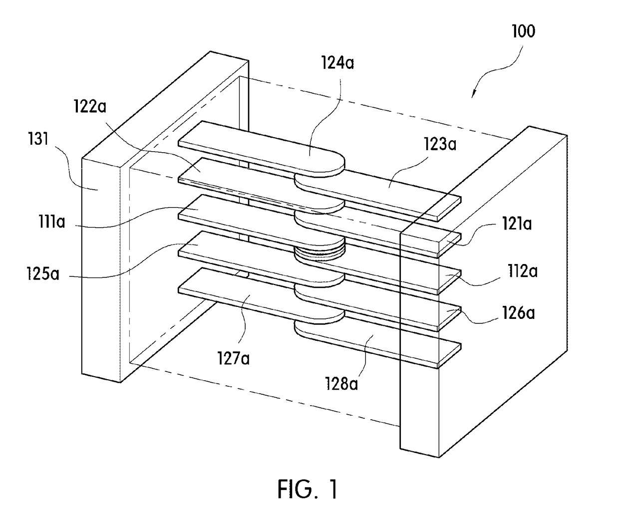
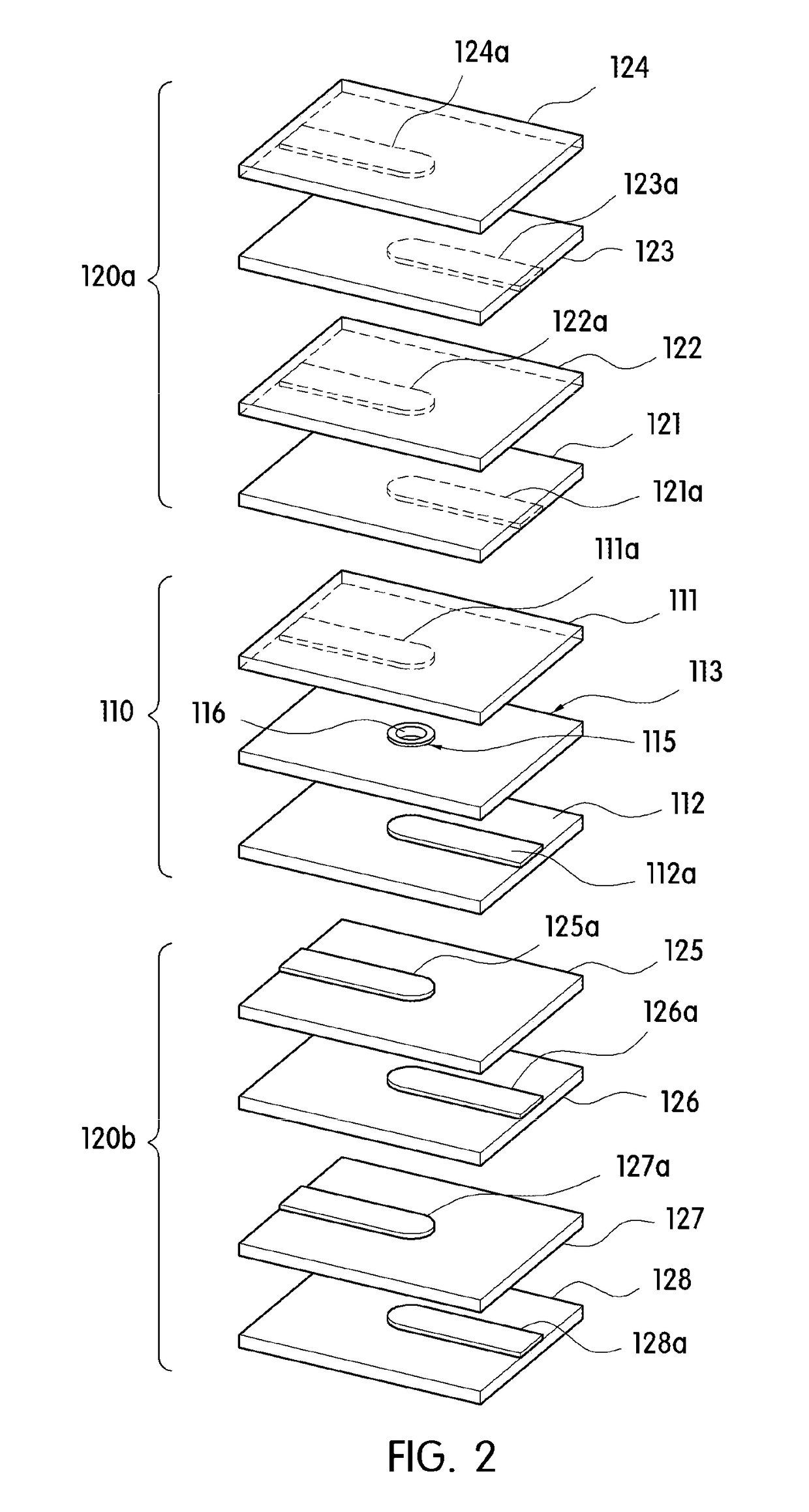
[0069]According to an embodiment of the present invention, an electric shock protection device 100, as shown in FIGS. 1 to 3, includes a sintered body, an electric shock protection unit 110, and capacitor layers 120a and 120b and the electric shock protection unit 110 may be a suppressor.

[0070]The electric shock protection device 100 is disposed between a human body contactable conductor and an internal circuit unit of an electronic device, does not cause dielectric breakdown when static electricity flows from the conductor, blocks th...


PUM

PropertyMeasurementUnit
thicknessaaaaaaaaaa
discharge start voltageaaaaaaaaaa
rated voltageaaaaaaaaaa

Abstract

Provided is an electric shock protection device disposed between a human body contactable conductor and an internal circuit unit of an electronic device. The electric shock protection device includes: a sintered body where a plurality of sheet layers stacked; an electric shock protection unit including at least one pair of inner electrodes disposed spaced a predetermined interval apart from each other inside the sintered body and a pore disposed between the inner electrodes; and at least one capacitor layer configured to pass communication signals flowing from the conductor.

Description

CROSS-REFERENCE TO RELATED APPLICATIONS[0001]The entire contents of Korean Patent Application Nos. 10-2014-0162858, filed on Nov. 20, 2014, 10-2015-0069286, filed on May 18, 2015, and 10-2015-0094273, filed on Jul. 1, 2015, are hereby incorporated by reference.BACKGROUND OF THE INVENTION[0002]The present invention disclosed herein relates to an electric shock protection device and a portable electronic device including the same, and more particularly, to an electric shock protection device for protecting a user from leakage current due to power, protecting an internal circuit from external electrostatic, and minimizing the attenuation of communication signals and delivering them, and a portable electronic device including the same.[0003]Recent portable electronic devices employ housings of a metal material increasingly in order to improve the aesthetics and durability.[0004]However, since such housings of a metal material have excellent electrical conductivity due to characteristics...

Claims


Application Information

Patent Timeline
Patent Type & Authority Patents(United States)
IPC IPC(8): H02H9/02G06F1/16H04M1/02H05K1/02H02H9/04H01L27/02
CPCG06F1/1656H04M1/02H01L27/0288H02H9/046H05K1/0259H04M1/026H01G2/14H01G4/12H01G4/30H01G4/35H01Q1/243H05K9/0016
Inventor KIM, TONG GIYU, JUN-SUHPARK, KYU HWANSUN, GUI NAMRYU, JAE SULEE, SEUNG CHUL
Owner AMOTECH
Why Eureka
Try Eureka