Tuner circuit

Inactive Publication Date: 2013-08-27
SAMSUNG ELECTRONICS CO LTD
View PDF32 Cites 0 Cited by
  • Summary
  • Abstract
  • Description
  • Claims
  • Application Information

AI Technical Summary

Benefits of technology

[0013]It is a still further object to provide a process and integrated tuning circuit using a buffer that produces a small driving current while minimizing the attenuation of the higher frequency characteristics of video signals.
[0014]These and other objects may be attained with a tuning circuit and process that uses a buffer installed within an integrated circuit (IC) providing small-current drive at a video output terminal. The tuning circuit has an RF converter

Problems solved by technology

I have found that absent the external buffer, the ability of the integrated tuning circuit deteriorates to the point that attenuation occurs in the

Method used


Image

  • Tuner circuit
  • Tuner circuit
  • Tuner circuit

Examples


Example

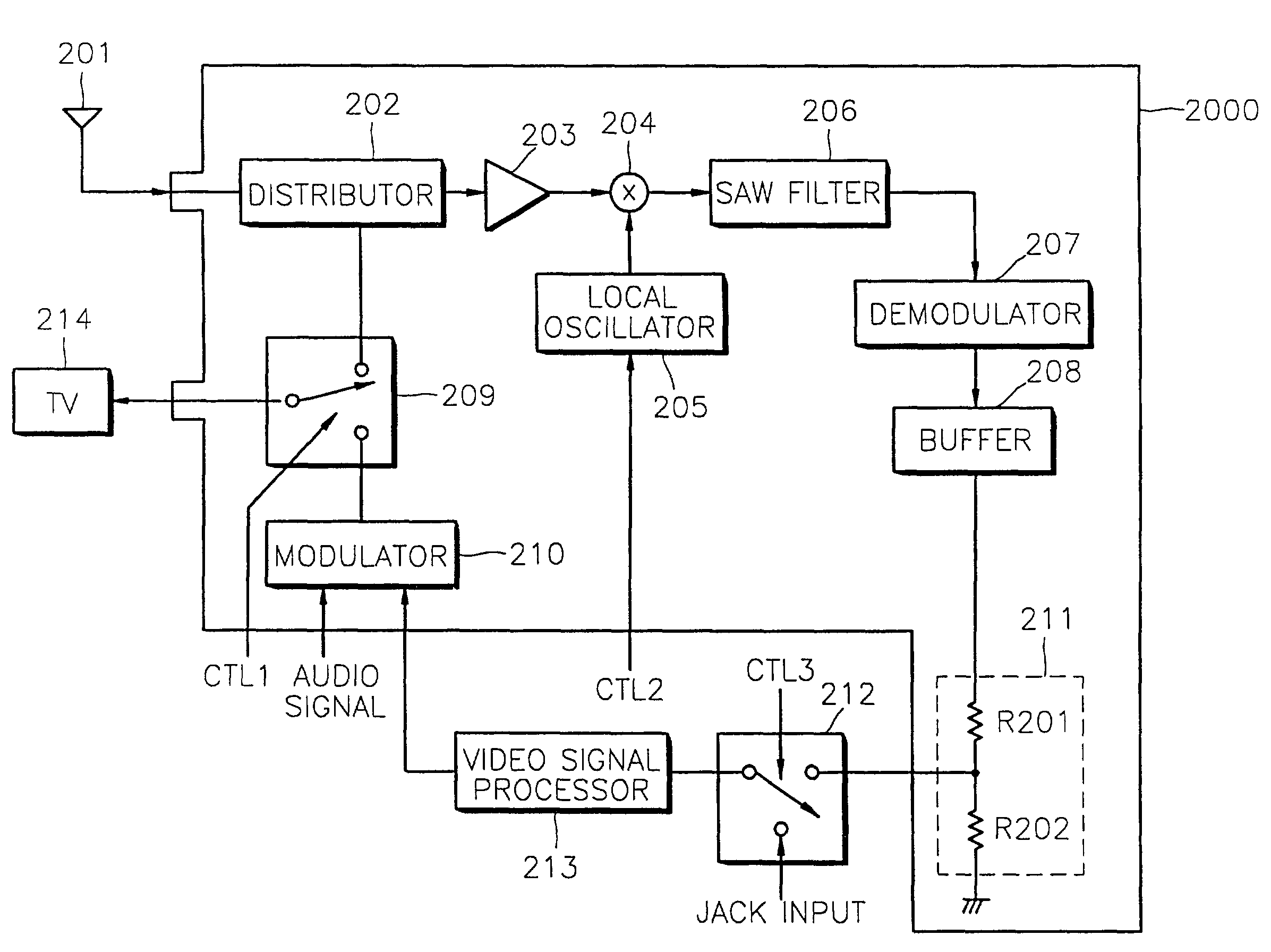
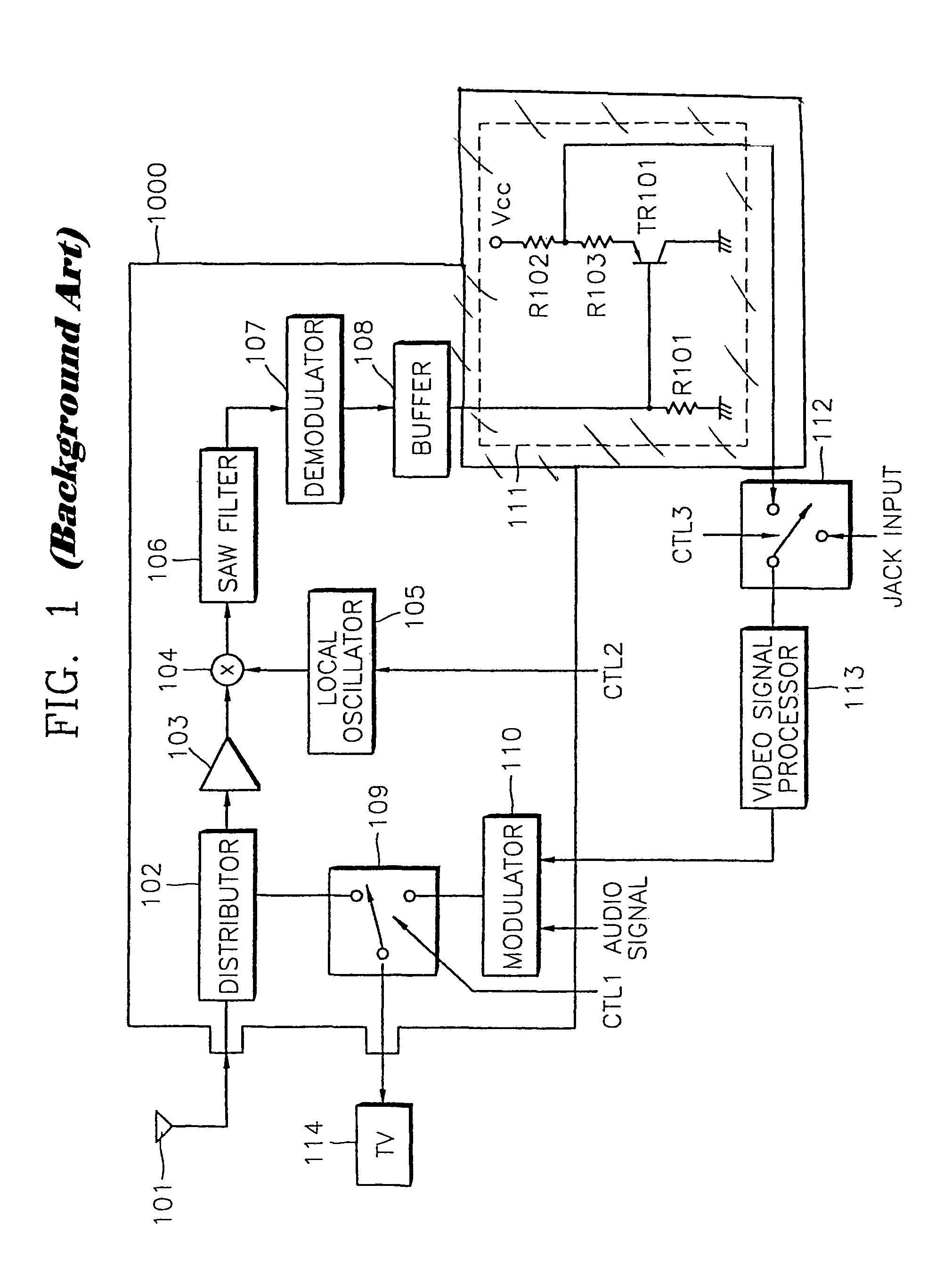
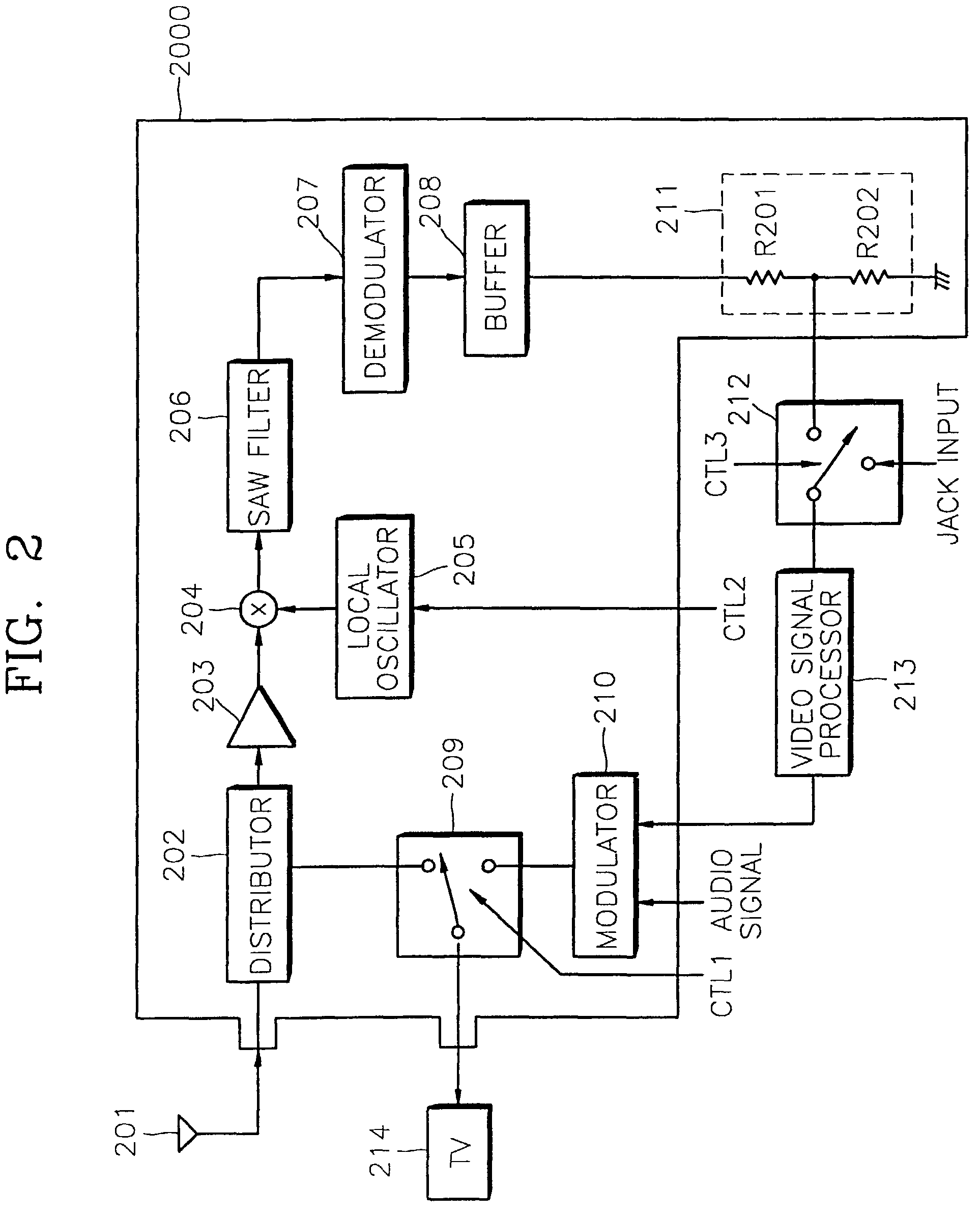
[0023]Turning now to the drawings, FIG. 1 illustrates tuner circuit 1000 with a radio frequency converter portion that uses a distributor 102, a TV / VCR switch 109, and a modulator 110. The tuning portion includes a RF amplifier 103, a mixer 104, and a local oscillator 105. The demodulation portion includes a SAW filter 106, a demodulator 107, a buffer 108, and an external buffer 111. Circuits external to tuner circuit 1000 include a tuner / jack input selection switch 112, a video signal processor 113, and an external output, e.g., television (TV) 114. When the TV / VCR switch 109 is switched to the TV mode, the broadcasting signal received from the distributor 102 is applied to TV 114 in response to a control signal CTL1, and a VCR mode, i.e., video / audio signals output from the video signal processor 113 of a VCR and an audio signal processor (not shown) of a VCR is modulated to a predetermined channel by the modulator 110, and then the modulated signal is output to the TV 114.

[0024]I...


PUM


Abstract

A tuner circuit and a method of designing a tuner circuit for removing a buffer circuit for video drive for increasing drive current capacitance added to an output terminal is provided, unlike a buffer for small-current drive installed in a tuner circuit. The method of designing a tuner circuit has a buffer installed in an integrated circuit (IC) of small-current drive in a video output terminal, and includes an RF converting portion, a tuning portion and a demodulation portion, in which a video output signal of the buffer in IC is input to an input circuit for processing a signal without an external buffer for drive, and the amount of attenuation of a signal at high frequency due to small drive current is measured to improve a frequency characteristic of a video signal in the tuner circuit in proportion to the amount of attenuation. Thus, an additional buffer for drive is not required, so that the number of devices is reduced, to thereby lower the material costs.

Description

CLAIM OF PRIORITY[0001]This application makes reference to, incorporates the same herein, and claims all benefits accruing under 35 U.S.C §119 from an application entitled Method Of Designing Tuner Circuit earlier filed in the Korean Industrial Property Office on 5 Sep. 1998, and there duly assigned Serial No. 98-36625 by that Office.[0002]This continuation application makes reference to, incorporates the same herein, and claims all benefits including under 35 U.S.C. §121 from a co-pending application entitled A TUNER CIRCUIT filed in the United States Patent & Trademark Office on the 7 Sep. 1999 and there duly assigned Ser. No. 09 / 391,614 now U.S. Pat. No. 6,483,554.BACKGROUND OF THE INVENTION[0003]1. Field of the Invention[0004]The present invention generally relates to image signal processing and image signal circuits, and, more particularly, to tuning signal processing and tuning circuits with small output drive currents exhibiting increased drive current capacitance at an outpu...

Claims


Application Information

Patent Timeline
IPC IPC(8): H04N5/268H04N5/44H04N5/50H04N5/60H04N5/775H04N9/64
CPCH04N5/4446H04N5/7755H04N5/60H04N9/64H04N5/50
Inventor KIM, CHUL-MIN
Owner SAMSUNG ELECTRONICS CO LTD
Why Eureka
Try Eureka