
Vehicle separation warning device

a technology for warning devices and vehicles, applied in traffic control systems, transportation and packaging, instruments, etc., can solve problems such as increased system cost, increased system complexity, and failure of vehicle operators to maintain an adequate separation distance from other vehicles

Inactive Publication Date: 2007-07-12
SCHOBER SCOTT
View PDF7 Cites 60 Cited by
  • Summary
  • Abstract
  • Description
  • Claims
  • Application Information

AI Technical Summary

Benefits of technology

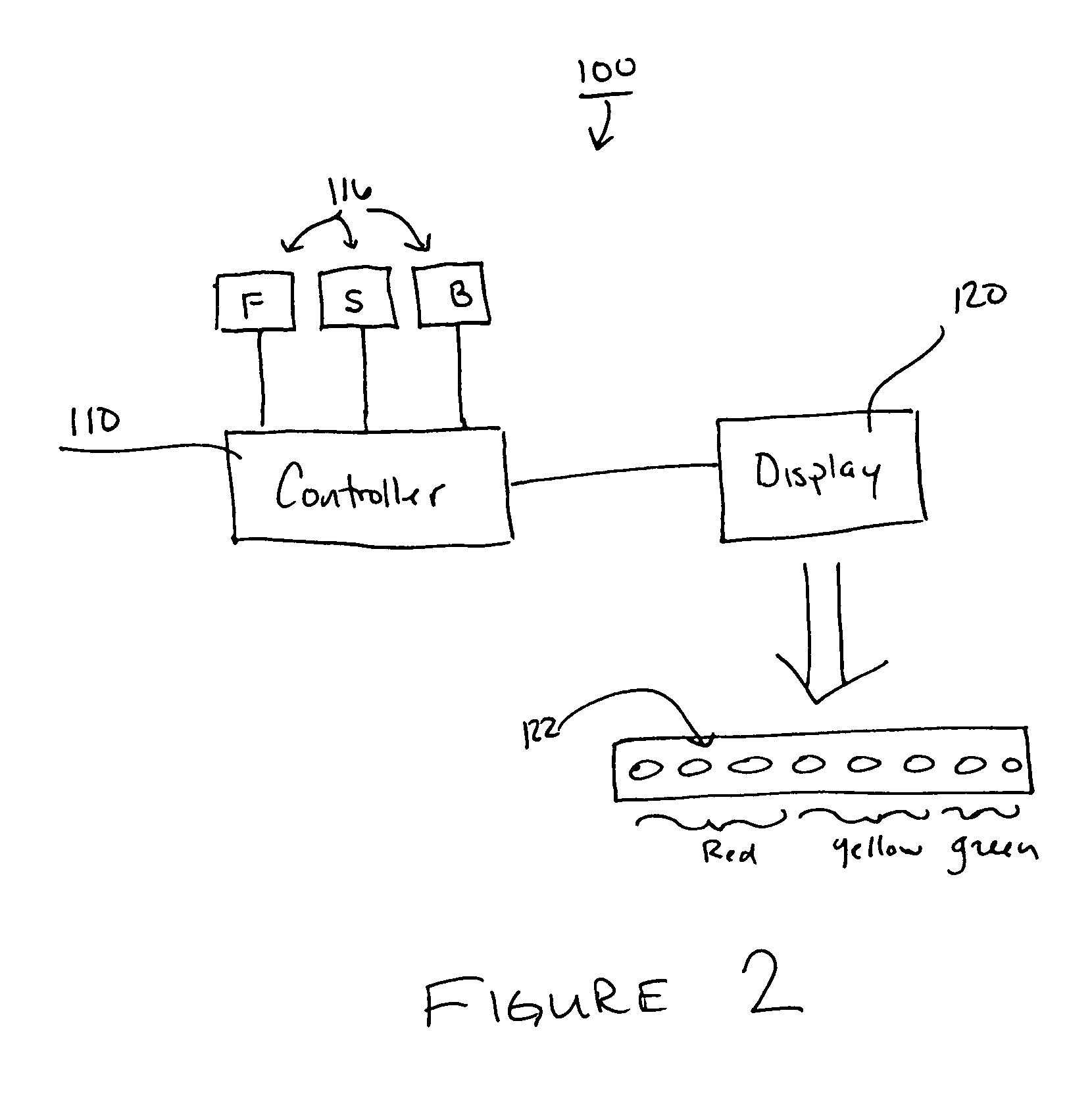
[0013] Embodiments of the invention may further provide a vehicle separation warning device. The separation device generally includes a Doppler distance measuring sensor positioned on a rearward facing surface of a first vehicle, the Doppler distance measuring sensor being configured to measure a distance between the first vehicle and a second vehicle following the first vehicle, a microprocessor controller in electrical communication with the distance measuring sensor and being configured receive input from the distance measuring sensor and generate outputs therefrom in accordance with an assembly language program, and visual warning devices positioned on the first vehicle and being in electrical communication with the microprocessor controller, the visual warning device including a plurality of multiple color LEDs. The controller is configured execute a program configured to conduct a method that includes; a) receiving a distance measurement in the controller from the Doppler distance measuring sensor, wherein the distance measurement is representative of the distance from the rear of the first vehicle to the front of the second vehicle; b) determining if the distance measurement is within one of a plurality of predetermined safety zone thresholds; c) illuminating a particular color LED on the visual warning devices in accordance with the determined predetermined safety zone thresholds; and d) repeating steps (a)-(c) between about 200 and about 1000 times per second.
[0014] Embodiments of the invention may further provide a vehicle separation warning device. Each microprocessor contains certain vehicle specific data including but not limited to vehicle type, vehicle weight, vehicle make and model etc. This information is transmitted to other microprocessors in nearby vehicles via radio type broadcast. These transmissions are also utilized to measure distance between...

Problems solved by technology

The most common cause of vehicle collisions is the failure of vehicle operators to maintain an adequate separation distance from other vehicles.
U.S. Pat. No. 3,681,750 to Larka (1972) discloses a passive device which detects ultrasonic signals; however, this device merely detects the presence of moving objects and does not inform the operator of the distance to these objects nor of their velocity, relative to the vehicle.
This greatly increases the cost of the system.
Also, use of multiple transducers increases the complexity of the system, thereby decreasing dependability.
This arrangement does not make effective use of the natural shape of the signal since, at very close distances, the width of the signal is very narrow as opposed to having a much larger width at greater distances.
Transducers which are located at different points on the vehicle require excessive lengths of cable to interconnect and coordinate their activities, creating logistical and design problems.
Stationary objects create false warnings which hinder rather than assist the operator.
They do not compensate for varying vehicle speeds, which necessarily dictate a greater warning distance.
All of the inventions are also unable to compensate for the addition of a trailer which would effectively void any protection provided by the system since any object located adjacent the trailer would go undetected.
Also, the trailer itself would cause a false warning since the transducer used to scan the rear area, if provided, would detect the reflected ultrasonic signal from the trailer.
All of the above noted inventions also utilize dedicated electrical circuits which do not allow for an operator to program in preferred warning distances.

Method used


Image

  • Vehicle separation warning device
  • Vehicle separation warning device
  • Vehicle separation warning device

Examples


Embodiment Construction

[0018] An automobile device which will signal a following vehicle that the separation distance between it and the VSID equipped (occupied) vehicle is either safe (green), becoming unsafe(yellow), hazardous (red) or collision imminent (blinking red). VSID (pronounced V-Sid) utilizes a Doppler Radar Speed Sensor to determine speed and distance of a following vehicle and based upon programmed algorithms notifies the following driver (as well as the occupied vehicles driver on a dashboard display) via a light display (tail light integrated or stand alone) information about safe following distance.

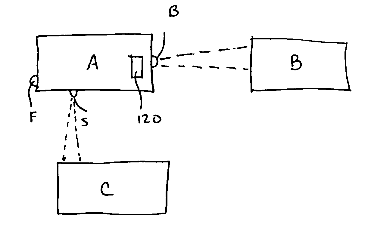
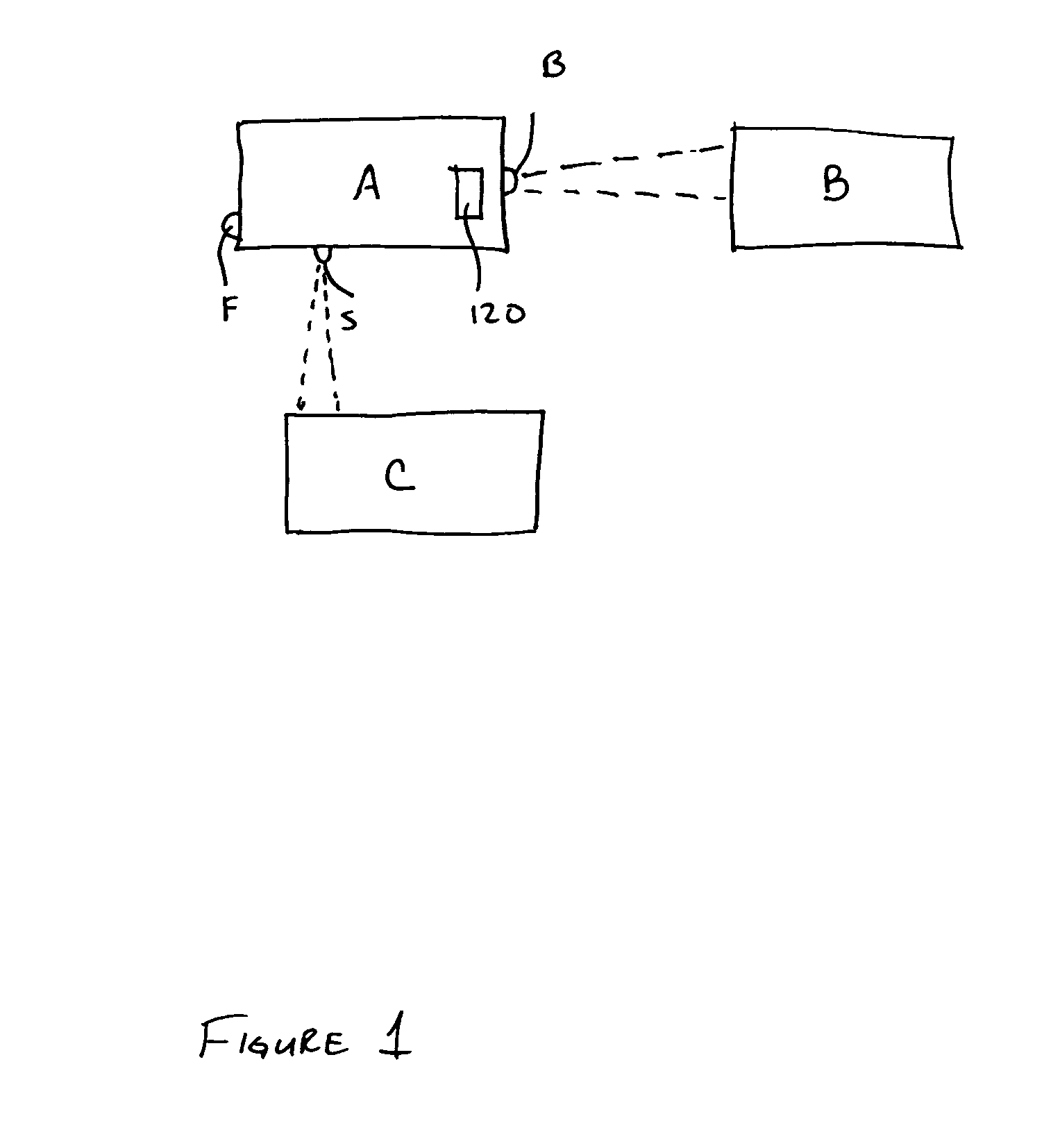
[0019]FIG. 1 illustrates general layout of an operational embodiment of the spatial separation apparatus 100 of the invention. The spatial separation apparatus 100 of the invention is illustrated as being positioned in vehicle A, and is operating to monitor and warn the drivers of vehicle B and C as to the spatial separation of vehicle B and vehicle C relative to vehicle A. The spatial separat...


PUM


Abstract

A method and apparatus for providing warnings related to vehicle separation. The warning device of the invention generally includes a distance measuring sensor positioned on a rearward facing surface of a first vehicle, the distance measuring sensor being configured to measure a distance between the first vehicle and a second vehicle following the first vehicle, a microprocessor controller in electrical communication with the distance measuring sensor and being configured receive input from the distance measuring sensor and generate outputs therefrom, and a visual warning device positioned on the first vehicle and being in electrical communication with the microprocessor controller. Generally, the controller of the device is configured to execute a program configured to conduct a method, wherein the method includes: a) receiving a distance measurement in the controller from the distance measuring sensor, wherein the distance measurement is representative of the distance from the rear of the first vehicle to the front of the second vehicle; b) determining if the distance measurement is within one of a plurality of predetermined safety zone thresholds; and c) illuminating the visual warning device in accordance with the determined predetermined safety zone thresholds.

Description

BACKGROUND OF THE INVENTION [0001] 1. Field of the Invention [0002] Embodiments of the invention generally relate to an apparatus and method for alerting a driver of a vehicle to dangerous conditions so that the driver of the vehicle may take corrective action. [0003] 2. Description of the Related Art [0004] The present invention relates to a distance separation system for vehicles. The invention has particular applicability to passenger cars, taxis, trucks, buses, and may be applied to water craft, aircraft, and other types of transportation mediums and military vehicle and motorized weapon systems as well. It is to be noted, however, that although the present invention is described below with respect to a vehicle in general, the invention is not intended to be limited to any particular vehicle. Rather, the present invention is contemplated as being applicable to all types and sizes of vehicles. [0005] The most common cause of vehicle collisions is the failure of vehicle operators ...

Claims


Application Information

Patent Timeline
IPC IPC(8): B60Q1/00
CPCB60Q1/525G08G1/16B60Q5/00G08G1/166B60Q1/535
Inventor SCHOBER, SCOTT
Owner SCHOBER SCOTT
Learn More