Systems and methods that utilize an active stub/parasitic whip antenna to facilitate mobile communication

a technology of parasitic whip and active stub, which is applied in the field of mobile communication, can solve the problems of pushing the existing analog technology to a capacity limit or ceiling, affecting the reliability of mobile devices, and requiring more expensive and complex components, so as to achieve the effect of preventing the overlap of the two antenna components

Active Publication Date: 2007-07-12
RPX CORP
View PDF5 Cites 6 Cited by
  • Summary
  • Abstract
  • Description
  • Claims
  • Application Information

AI Technical Summary

Benefits of technology

[0010] The present invention facilitates transmission and / or reception of radio frequency (RF) signals via mobile communications devices (e.g., cellular telephone). The systems and methods provide a relatively compact antenna for mobile communication devices with limited physical volume, or footprint. The present invention employs a simple antenna design that reduces antenna wear, which can be more reliable, easier to manufacture and can reduce cost. Additionally, the present invention can yield higher antenna gain and better radiation efficiency than conventional systems and does not require a matching circuit to achieve multi-band resonances. Furthermore, the present invention is adaptable to be incorporated into virtually any wireless communication device.
[0013] In accordance with another aspect of the present invention, when the second antenna component (e.g., parasitic whip) is retracted, it is detuned from the first antenna component (e.g., active stub). Detuning can be accomplished by employing a detuning circuit (e.g., matching network) or by utilizing a non-conductive end affixed to the end of the parasitic whip to prevent overlapping of the two antenna components.

Problems solved by technology

However, within a relatively short period of time, millions of new mobile communications subscribers, demanding more and more airtime, pushed the existing analog technology to a capacity limit or ceiling.
WCDMA and TD-SCDMA represent more complex enhancements that can entail more costly and complex components, new network designs, and longer verification and validation periods.
One obstacle confronted by mobile device designers is the need to provide more reliable, easier to manufacture, and lower cost antennas for smaller mobile devices, which have limited physical volumes or a limited footprint for antennas.

Method used


Image

  • Systems and methods that utilize an active stub/parasitic whip antenna to facilitate mobile communication
  • Systems and methods that utilize an active stub/parasitic whip antenna to facilitate mobile communication
  • Systems and methods that utilize an active stub/parasitic whip antenna to facilitate mobile communication

Examples


Embodiment Construction

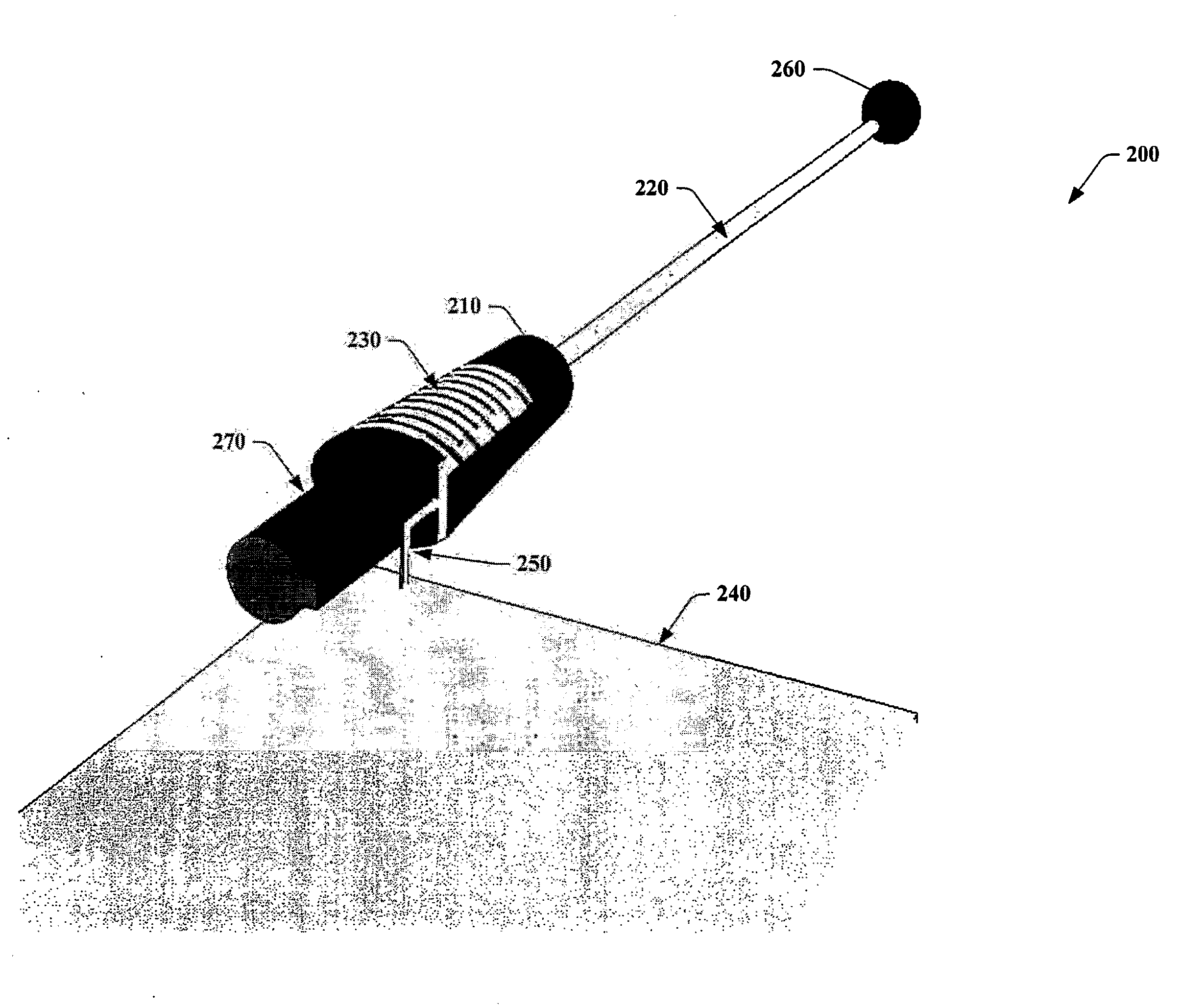
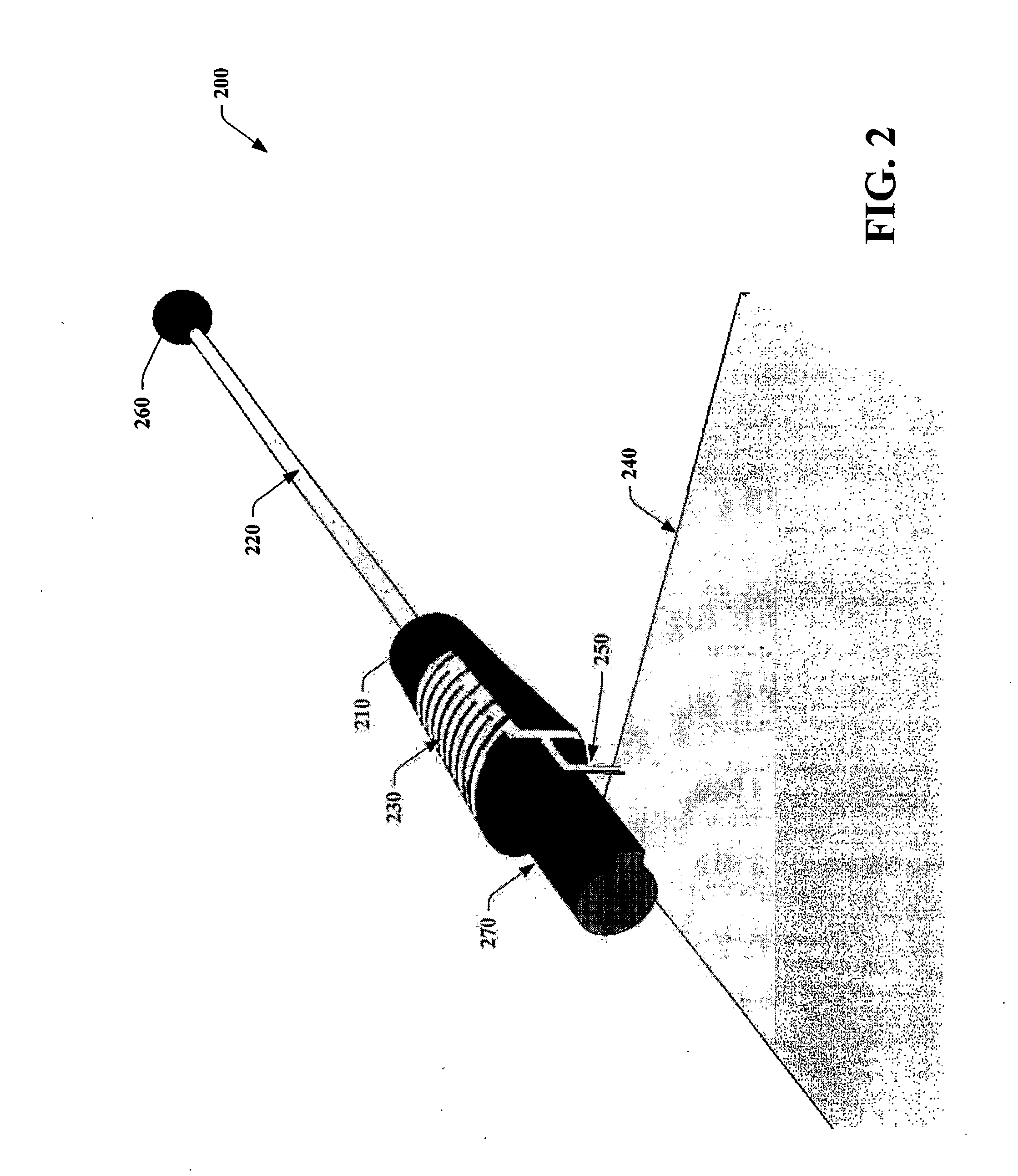
[0029] The present invention relates to systems and methods that transmit and / or receive radio frequency (RF) signals via mobile communication devices (e.g. a cellular phone). In particular, the systems and methods provide a relatively compact antenna structure for mobile devices with limited physical volume (e.g., footprint), wherein the antenna structure can include an active stub and a parasitic whip. The antenna structure of the present invention does not require a mechanical interface between the active stub and parasitic whip to provide a conductive connection to the whip when it is in an extended position. Since the mechanical interface is not employed, the present invention provides a simple antenna design, which reduces antenna wear, is more reliable, easier to manufacture, and reduces cost.

[0030] The present invention is now described with reference to the drawings, wherein like reference numerals are used to refer to like elements throughout. In the following description...


PUM


Abstract

The present invention provides systems and methods that facilitate transmission and / or reception of radio frequency (RF) signals within a mobile communications device. The systems and methods include a first antenna component such as an active stub that comprises one or more active elements and a second antenna component such as a parasitic whip that is electromagnetically coupled to the first antenna component. The systems and methods provide a relatively compact antenna structure for mobile devices with limited physical volume, or footprint. The antenna structure does not require a mechanical interface (e.g., a galvanic connection) between the active stub and parasitic whip to provide a conductive connection to the whip when it is in an extended position. The novel systems and methods yield reduced antenna wear, higher antenna gain and better radiation efficiency than conventional systems and do not require a matching circuit to achieve multi-band resonances.

Description

TECHNICAL FIELD [0001] The present invention generally relates to mobile communication. More particularly, the present invention relates to employing an antenna structure that utilizes an active stub and a parasitic whip as a radiator within a mobile communications device. BACKGROUND OF THE INVENTION [0002] Early mobile communication devices employed analog radio transmission such as Advanced Mobile Phone System (AMPS), for example. Such analog technologies were sufficient for an emerging mobile communications consumer market. However, within a relatively short period of time, millions of new mobile communications subscribers, demanding more and more airtime, pushed the existing analog technology to a capacity limit or ceiling. As a consequence, dropped calls and busy signals became common, which fueled a demand for an improved mobile communication network. [0003] In response to the demand, industry developed digital wireless technologies that could accommodate the increased network...

Claims


Application Information

Patent Timeline
Patent Type & Authority Applications(United States)
IPC IPC(8): H01Q1/24H01Q1/36
CPCH01Q1/362H01Q1/242
Inventor FOSSETT, LARRY
Owner RPX CORP
Why Eureka
Try Eureka