Method for forming an ultrasonic transducer, and associated apparatus

a micro-machined, ultrasonic technology, applied in the field of ultrasonic transducers, can solve the problems of limiting the forming configuration of high-frequency transducer arrays having smaller dimensions, adversely affecting the acoustic signals generated by the pmut device, and reducing the flexural and/or vibration of the pmut membrane, so as to facilitate the transmission and reception of acoustic signals. , the effect of facilitating flexure and/

Active Publication Date: 2014-04-08
RES TRIANGLE INST
View PDF13 Cites 6 Cited by
  • Summary
  • Abstract
  • Description
  • Claims
  • Application Information

AI Technical Summary

Benefits of technology

[0010]The above and other needs are met by aspects of the present disclosure, wherein one such aspect relates to a method of forming a piezoelectric ultrasonic transducer apparatus. Such a method comprises depositing a first electrode on a dielectric layer disposed on a primary substrate. A piezoelectric material is deposited on the first electrode, and a second electrode is deposited on the piezoelectric material, so as to form a transducer device. At least the piezoelectric material is patterned such that a portion of the first electrode extends laterally outward therefrom. The primary substrate and the dielectric layer are etched to form a first via extending to the laterally outward extending portion of the first electrode. A first conductive material is deposited to substantially fill the first via, wherein the first conductive material forms an electrically-conductive engagement with the laterally outward extending portion of the first electrode. The primary substrate is etched to define a second via extending therethrough, and forming the air-backed cavity of the pMUT device, wherein the second via is laterally spaced apart from the first via. The air-backed cavity of the pMUT device associated with the piezoelectric element thus facilitates flexure and / or vibration of the pMUT membrane when voltage is applied to the piezoelectric material through the first and second electrodes, or when an acoustic echo is received by or otherwise acts on the pMUT membrane. Such a configuration thus facilitates transmission and reception of acoustic signals by the pMUT device.

Problems solved by technology

However, such approaches may be limiting for high frequency transducer arrays having smaller dimensions.
Such a configuration may not be desirable for forming though-wafer interconnects in line with the transducer elements (i.e., through the pMUT air-backed cavity).
Such fatigue could result in cracking or delamination of the metal layer and failure of the electrically-conductive engagement therebetween and would thus create an open circuit condition between the first / bottom electrode of the pMUT device and the IC, flex cable or redistribution substrate engaged therewith, or may adversely affect the acoustic signals generated by the pMUT device.
Such a configuration may particularly adversely affect smaller membranes required for high frequency operation.
Such a configuration, as a result, may increase the resonance frequency, but could also undesirably reduce the acoustic output due to increased stiffness of the vibrating membrane resulting from the reduced free width and increased thickness thereof.

Method used


Image

  • Method for forming an ultrasonic transducer, and associated apparatus
  • Method for forming an ultrasonic transducer, and associated apparatus
  • Method for forming an ultrasonic transducer, and associated apparatus

Examples


Embodiment Construction

[0019]The present disclosure now will be described more fully hereinafter with reference to the accompanying drawings, in which some, but not all aspects of the disclosure are shown. Indeed, the disclosure may be embodied in many different forms and should not be construed as limited to the aspects set forth herein; rather, these aspects are provided so that this disclosure will satisfy applicable legal requirements. Like numbers refer to like elements throughout.

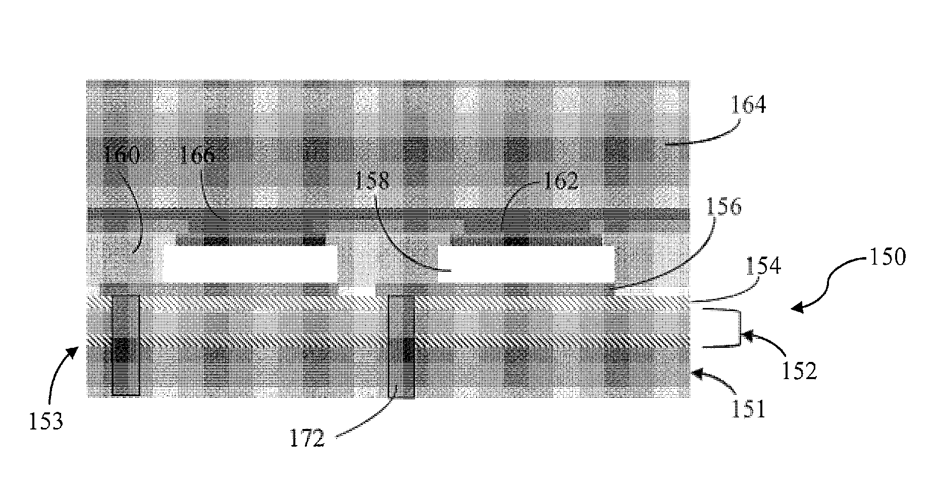
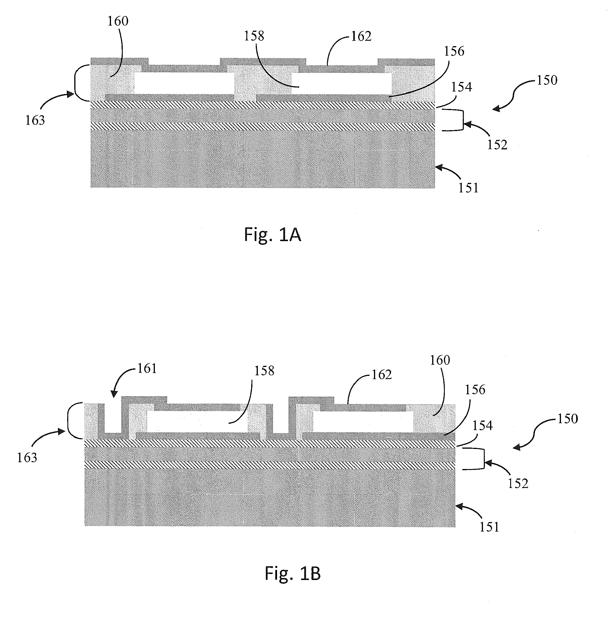
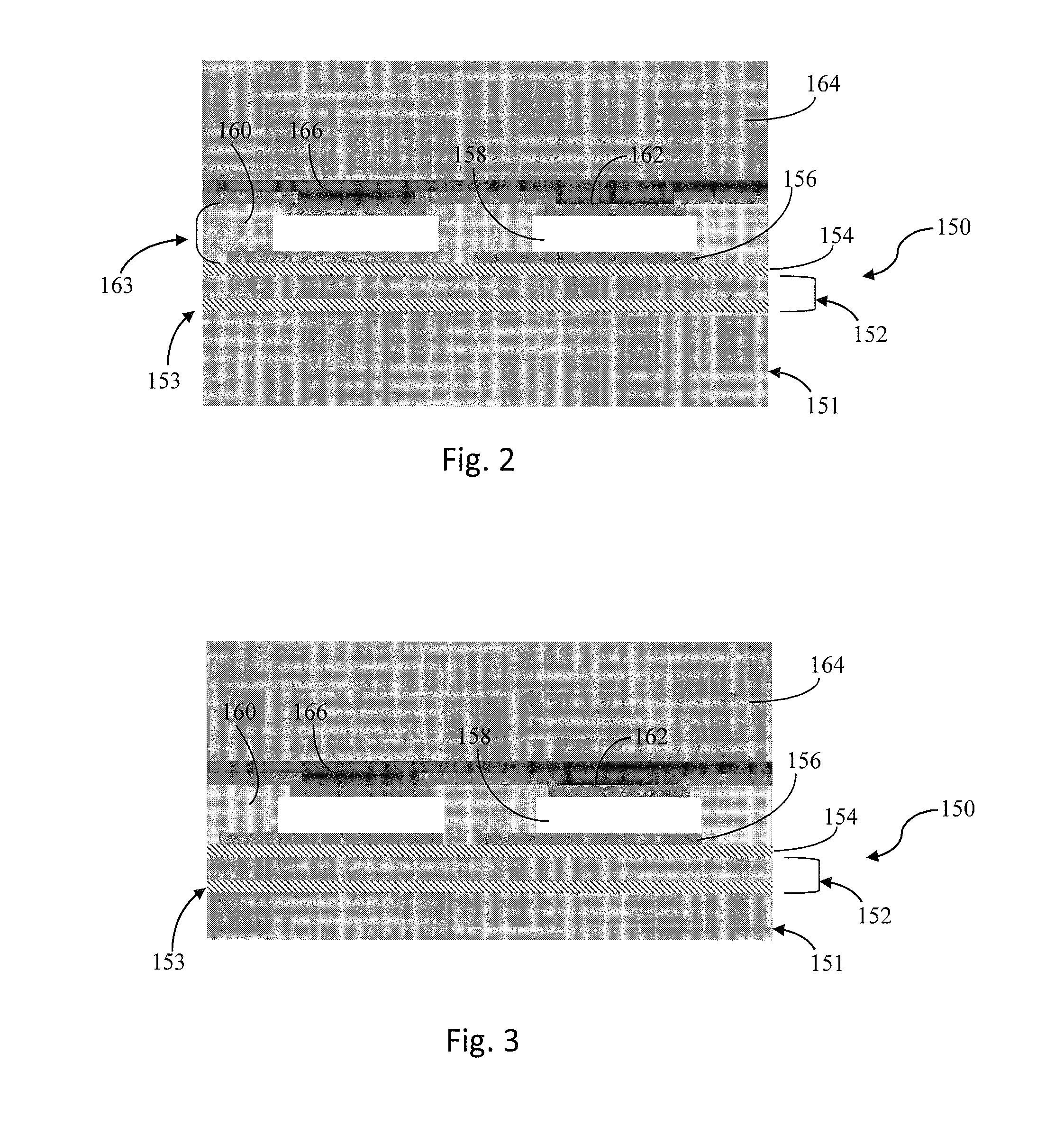
[0020]Aspects of the present disclosure are generally directed to methods for forming an electrically-conductive member extending through a substrate to a transducer device supported thereby, and into electrically-conductive contact with the first / bottom electrode of the transducer device formed on the opposing surface of the substrate. More particularly, the first / bottom electrode layer is configured to extend laterally outward of the transducer device, such that the electrically-conductive member formed in electrically-co...


PUM


Abstract

A method is provided for forming a piezoelectric ultrasonic transducer apparatus having a first electrode deposited on a dielectric layer disposed on a primary substrate. A piezoelectric material is deposited between the first electrode and a second electrode, to form a transducer device. At least the piezoelectric material is patterned such that a portion of the first electrode extends laterally outward therefrom. The primary substrate and the dielectric layer are etched to form a first via extending to the laterally outward portion of the first electrode, and a first conductive material is deposited to substantially fill the first via and form an electrically-conductive engagement with the laterally outward portion of the first electrode. The primary substrate is etched to define a second via extending therethrough, wherein the second via is laterally spaced apart from the first via. An associated method and apparatus are also provided.

Description

BACKGROUND OF THE DISCLOSURE[0001]1. Field of the Disclosure[0002]Aspects of the present disclosure relate to ultrasonic transducers, and, more particularly, to a method of forming a piezoelectric micromachined ultrasonic transducer defining an air-backed cavity, and an associated apparatus.[0003]2. Description of Related Art[0004]Some micromachined ultrasonic transducers (MUTs) may be configured, for example, as a piezoelectric micromachined ultrasonic transducer (pMUT) disclosed in U.S. Pat. No. 7,449,821 assigned to Research Triangle Institute, also the assignee of the present disclosure, which is also incorporated herein in its entirety by reference.[0005]The formation of a pMUT device, such as the pMUT device defining an air-backed cavity as disclosed in U.S. Pat. No. 7,449,821, may involve the formation of an electrically-conductive connection between the first electrode (i.e., the bottom electrode) of the transducer device, wherein the first electrode is disposed on the front...

Claims


Application Information

Patent Timeline
Patent Type & Authority Patents(United States)
IPC IPC(8): H01L41/047H01L41/053H01L41/107H03H9/15B31D3/00
CPCB06B1/0607G10K11/004H01L41/0973H01L41/332H01L41/0474H01L41/293H01L41/29H10N30/2047H10N30/06H10N30/082B06B1/06G10K11/00H10N30/80H10N30/874H10N30/063
Inventor DAUSCH, DAVIDGOODWIN, SCOTT H.
Owner RES TRIANGLE INST
Why Eureka
Try Eureka