Tire electronics assembly having a multi-frequency antenna

a technology of electronics assembly and antenna, which is applied in the direction of vehicle tyre testing, instruments, roads, etc., can solve the problems of affecting the performance of electronics assemblies and associated antenna structures, subjecting components to excessive heat, tension and other dynamic forces, and affecting the overall performance of electronics assemblies

Active Publication Date: 2005-12-15
MICHELIN RECH & TECH SA
View PDF5 Cites 17 Cited by
  • Summary
  • Abstract
  • Description
  • Claims
  • Application Information

AI Technical Summary

Benefits of technology

[0008] In view of the recognized features encountered in the prior art and addressed by the present subject matter, an improved electronics assembly for integration with a tire structure has been developed. Such an electronics assembly includes antenna features that effect RF communication at multiple different frequency levels.

Problems solved by technology

This is due in part to the fact that RF regulations and standards are not globally homogeneous.
Such components are provided relative to a location that is constantly moving and flexing, thus subjecting the components to excessive heat as well as tension and other dynamic forces.
Such forces may yield a potential for damaging the electronics assemblies and associated antenna structure.
A particular example of such undesirable damage corresponds to an antenna being separated from its associated electronic assembly and / or RF device.
While various tire electronics systems and antenna structures therefor have been developed, no design has emerged that generally encompasses all of the desired characteristics as hereafter presented in accordance with the subject technology.

Method used


Image

  • Tire electronics assembly having a multi-frequency antenna
  • Tire electronics assembly having a multi-frequency antenna
  • Tire electronics assembly having a multi-frequency antenna

Examples


Embodiment Construction

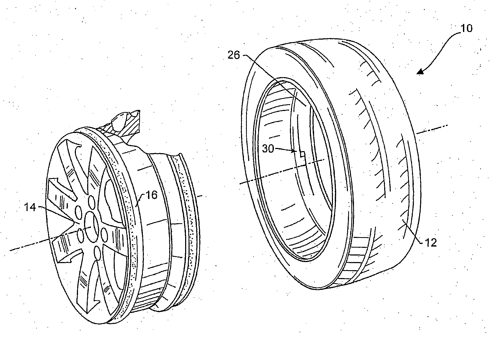
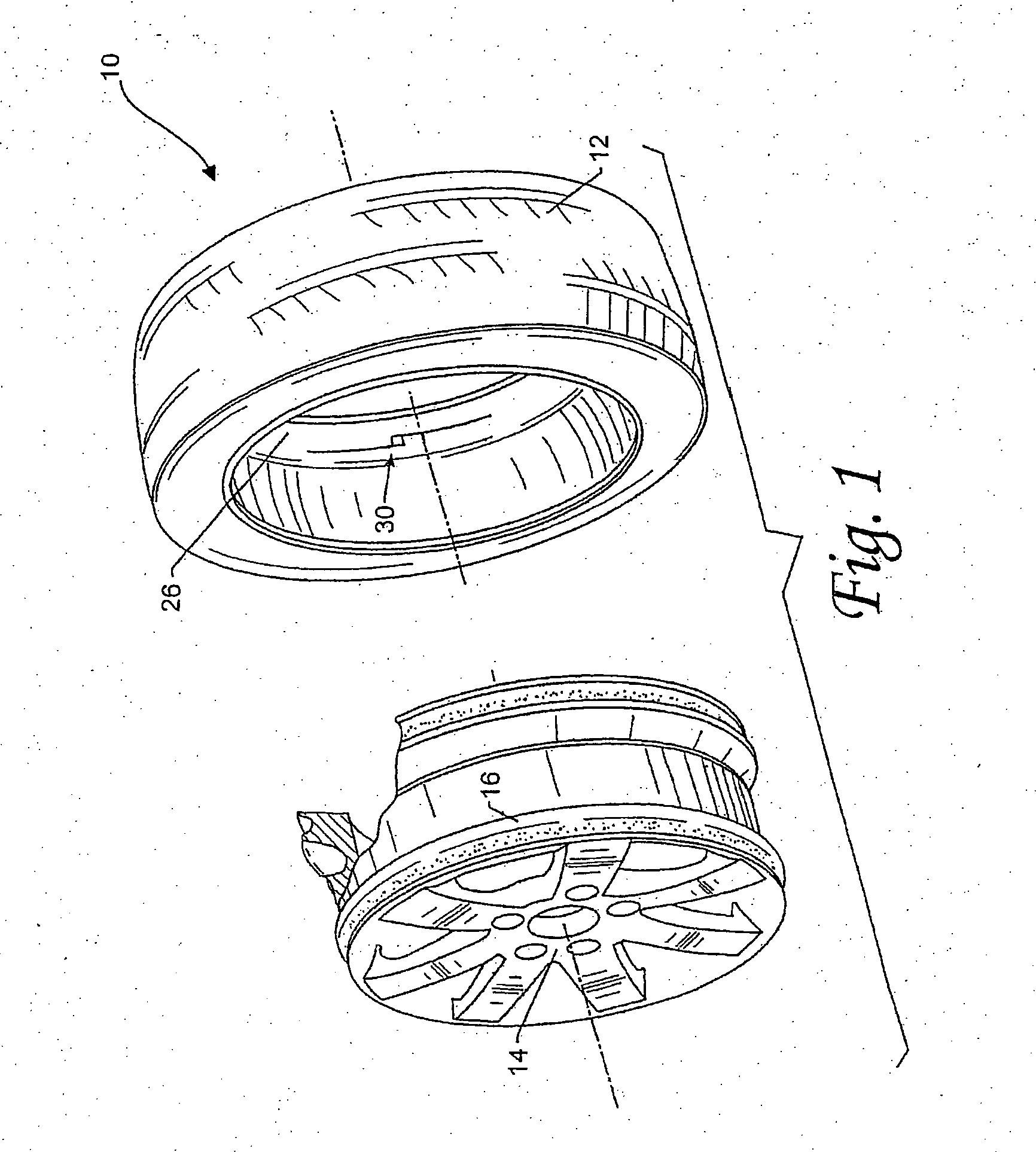
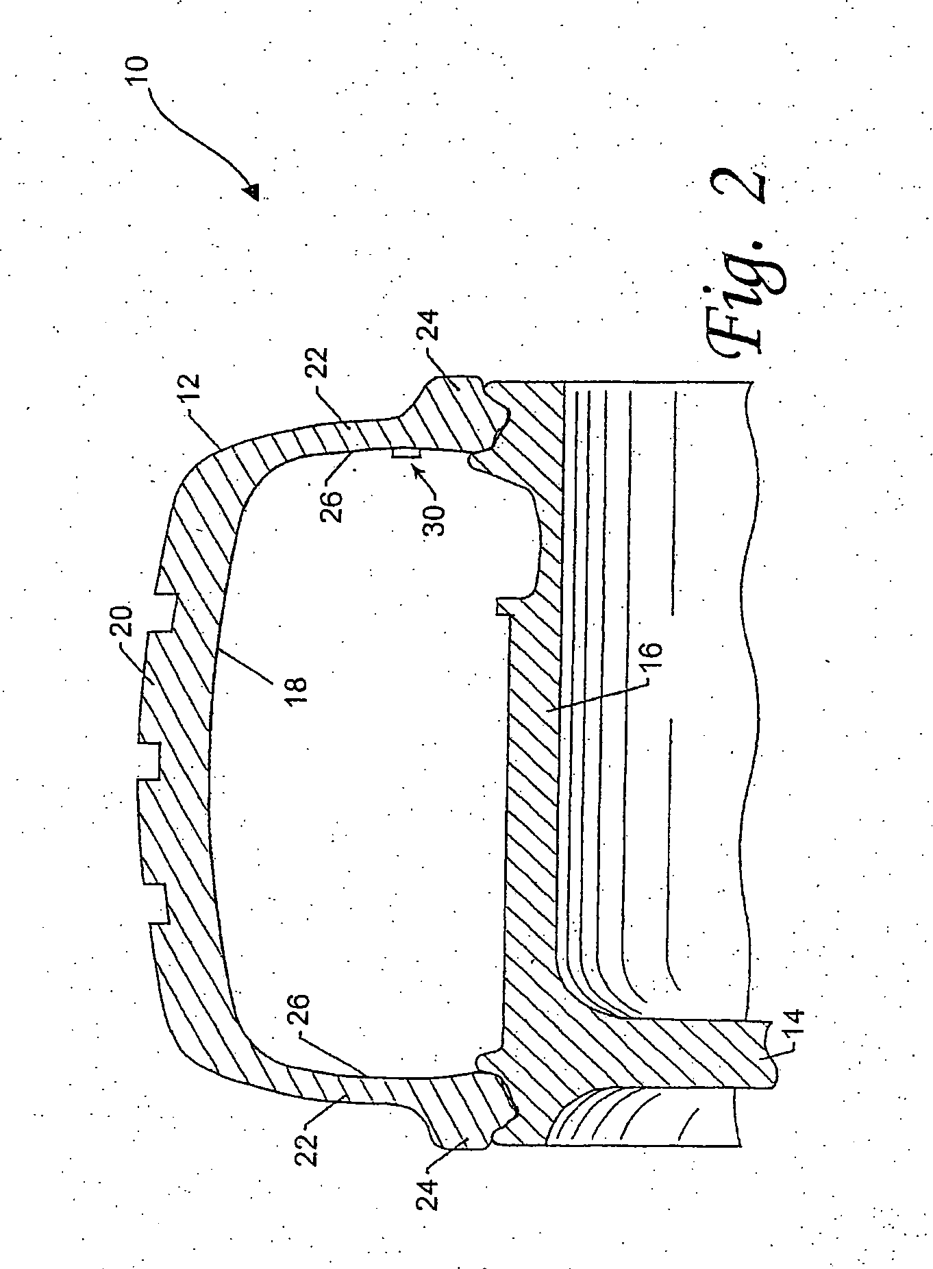
[0028] As discussed in the Summary of the Invention section, the present invention is particularly concerned with tire electronics assemblies that relay various information related to tire identification and / or measurements of selected physical conditions of a tire. FIGS. 1 and 2 illustrate exemplary tire assemblies, including such electronics assemblies positioned relative to the interior of a tire structure. The subject tire electronics assemblies utilize improved antenna configurations that allow for effective signal propagation at multiple frequency levels. Such multi-frequency antenna configurations may be designed with improved mechanical robustness and versatile communication capabilities. Exemplary embodiments of such electronics assemblies are illustrated in FIGS. 3A, 3B and 6A-9, respectively.

[0029] Selected combinations of aspects of the disclosed technology correspond to a plurality of different embodiments of the present invention. It should be noted that each of the e...


PUM


Abstract

A tire assembly with integrated electronic components includes a tire structure and an integrated electronics assembly, which preferably includes at least a radio frequency (RF) device and a multi-frequency antenna that enables wireless communication in at least first and second resonant frequency bands. Such multi-frequency antenna further comprises at least first and second antenna wires connected to the RF device, thus facilitating the transmission of RF signals which may include information such as tire identification information or measured condition information such as tire temperature, pressure, and other characteristics. The first and second antenna wires preferably function together as at least two dipole antennas, for example, two half-wave dipole antennas, or one half-wave dipole antenna and one three-half-wave dipole antenna. A two-wire configuration may be more readily implemented and also designed to reduce strains concentrated at the connection point(s) between the RF device and the antenna wires.

Description

FIELD OF THE INVENTION [0001] The present invention generally concerns tire electronics assemblies that communicate various information related to tire identification and / or measurements of selected physical conditions of a tire. More particularly, the subject tire electronics assemblies utilize improved antenna configurations that allow for effective signal propagation at multiple frequency levels. Such multi-frequency antenna configurations may be designed with improved mechanical robustness and versatile communication capabilities. BACKGROUND OF THE INVENTION [0002] The incorporation of electronic devices with pneumatic tire structures yields many practical advantages. Tire electronics may include sensors and other components for relaying tire identification parameters and also for obtaining information regarding various physical parameters of a tire, such as temperature, pressure, number of tire revolutions, vehicle speed, etc. Such performance information may become useful in t...

Claims


Application Information

Patent Timeline
Patent Type & Authority Applications(United States)
IPC IPC(8): B60C23/00B60C23/04H01Q1/22H01Q1/32H01Q9/16
CPCB60C23/0452B60C23/0493H01Q5/371H01Q1/325H01Q9/16H01Q1/2241
Inventor ADAMSON, JOHN DAVIDKING, PATRICK F.
Owner MICHELIN RECH & TECH SA
Why Eureka
Try Eureka