Device for tracking pupil of eyeball using intensity changes of reflected light from eyeball and image display using the same

a technology of intensity changes and eyeballs, applied in the field of tracking the position of eyeballs, can solve the problems of reduced tracking accuracy of pupils, unavoidable dependence on tracking accuracy, and increased manufacturing costs, and achieve the effect of improving the technique of tracking the position of pupils

Inactive Publication Date: 2007-07-12
BROTHER KOGYO KK
View PDF10 Cites 62 Cited by
  • Summary
  • Abstract
  • Description
  • Claims
  • Application Information

AI Technical Summary

Benefits of technology

[0017] It is therefore an object of the present invention to improve the technique of tracking the position of a pup

Problems solved by technology

For this reason, this exemplary conventional approach is likely to cause a problem that a reduction in luminance of the imaging light leads to an undesirable reduction in tracking accuracy of a pupil position due to a shortage of an amount of the reference light, resulting from unavoidable dependency of the tr

Method used


Image

  • Device for tracking pupil of eyeball using intensity changes of reflected light from eyeball and image display using the same
  • Device for tracking pupil of eyeball using intensity changes of reflected light from eyeball and image display using the same
  • Device for tracking pupil of eyeball using intensity changes of reflected light from eyeball and image display using the same

Examples


first embodiment

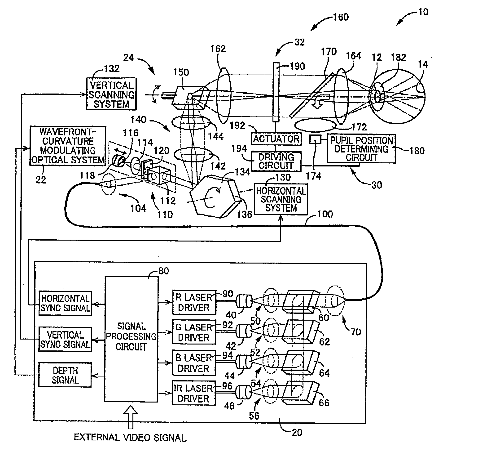
[0144] Referring first to FIG. 1, there is schematically illustrated a retinal scanning display (hereinafter, abbreviated to “RSD”) constructed according to the present invention.

[0145] This RSD is a type of an image display apparatus of which allows a laser beam to be projected onto a retina 14 through a pupil 12 of a viewer's eye (i.e., an eyeball 10), to thereby let the viewer to perceive a display object via a virtual image.

[0146] More specifically, this RSD allows a laser beam to pass through the pupil 12 and to be focused on the retina 14, with its wavefront curvature and light intensity being properly modulated, and to be two-dimensionally scanned on the retina 14, to thereby project an image directly onto the retina 14.

[0147] As illustrated in FIG. 1, this RSD includes a light source unit 20, and a wavefront-curvature modulating optical system 22 and a scanning unit 24 both of which are disposed between the light source unit 20 and the viewer's eye 10, as arrayed in the de...

second embodiment

[0260] Next, the present invention will be described.

[0261] The present embodiment is common to the first embodiment with respect to many elements, and is different from the first embodiment only with respect to the configuration for shifting the optical axis. Therefore, only the different elements of the present embodiment from those of the first embodiment will be described below in greater detail, while the common elements of the present embodiment to those of the first embodiment will be omitted in detailed description by reference using the identical reference numerals or names.

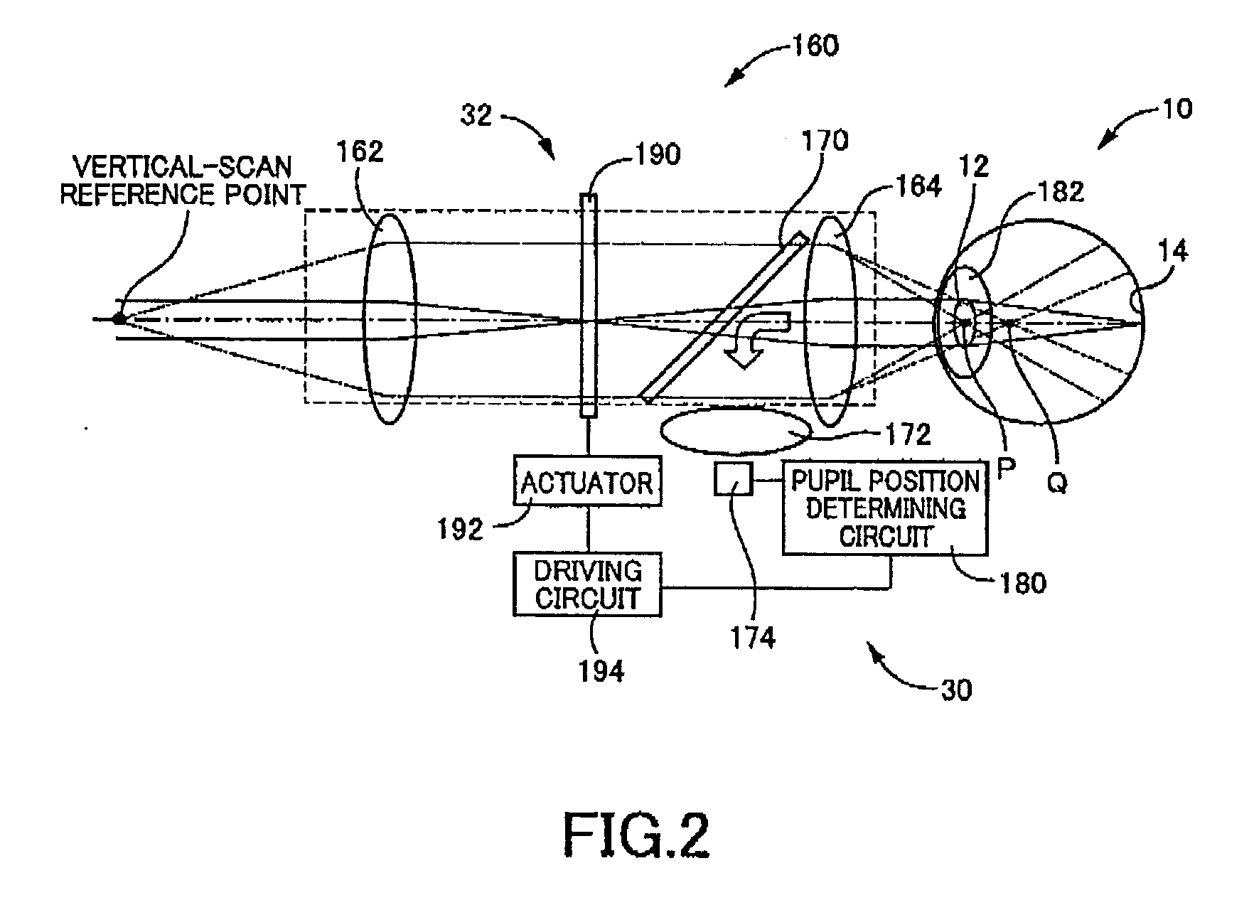
[0262] In the first embodiment, the variable prism 190 enables the direction of the optical axis of the imaging light to be shifted or deflected, to thereby control the entrance position of the imaging light on the eye 10 to match with the position of the pupil 12.

[0263] In contrast, in the present embodiment, as illustrated in FIG. 10, for the direction of the optical axis of the imaging light to be s...

third embodiment

[0272] Next, the present invention will be described.

[0273] The present embodiment is common to the first embodiment with respect to many elements, and is different from the first embodiment only with respect to the configuration for shifting the optical axis of the imaging light. Therefore, only the different elements of the present embodiment from those of the first embodiment will be described below in greater detail, while the common elements of the present embodiment to those of the first embodiment will be omitted in detailed description by reference using the identical reference numerals or names.

[0274] In the first embodiment, the variable prism 190 enables the direction of the optical axis of the imaging light to be shifted or deflected, to thereby control the entrance position of the imaging light on the eye 10.

[0275] In contrast, in the present embodiment, a movable mirror inclined with respect to the optical axis of the imaging light is translated or shifted parallel, ...


PUM


Abstract

A technique is disclosed of tracking a position of a pupil of a viewer's eyeball, by directing light toward the eyeball and using a portion of the light reflected from the eyeball. In the technique, the detection is performed of the intensity of a reflected light beam which is a portion of a light beam entering the eyeball which is reflected therefrom. An intensity signal indicative of the intensity of the reflected light beam is produced. The pupil position is tracked based on intensity changes of the reflected light beam represented by the intensity signal.

Description

CROSS-REFERENCE TO RELATED APPLICATIONS [0001] This application is based on Japanese Patent Application No. 2004-238994 filed Aug. 19, 2004, and International Application No. PCT / JP2005 / 014719 filed Aug. 11, 2005, the contents of which are incorporated hereinto by reference. [0002] This application is a continuation-in-part application of International Application No. PCT / JP2005 / 014719 filed Aug. 11, 2005, now pending, which was published in Japanese under PCT Article 21 (2).BACKGROUND OF THE INVENTION [0003] 1. Field of the Invention [0004] The invention relates to techniques of tracking the position of a pupil of an eyeball, by directing light toward the eyeball and using a portion of the light reflected from the eyeball. [0005] 2. Description of the Related Art [0006] Techniques have been in existence which are capable of tracking or monitoring the position of a pupil of an eyeball, by directing light toward the eyeball and using a portion of the light reflected from the eyeball....

Claims


Application Information

Patent Timeline
IPC IPC(8): A61B3/10
CPCA61B3/02G02B27/0093A61B3/113
Inventor YAMADA, SHOJI
Owner BROTHER KOGYO KK
Why Eureka
Try Eureka