Surface emitting device

a surface emitting device and surface technology, applied in the direction of lighting and heating apparatus, planar/plate-like light guides, instruments, etc., can solve the problems of insufficient illumination, difficult component layout, and large system size, so as to reduce the size and reduce the protruding amount of the light entrance portion

Inactive Publication Date: 2007-07-12
ALPS ALPINE CO LTD
View PDF10 Cites 76 Cited by
  • Summary
  • Abstract
  • Description
  • Claims
  • Application Information

AI Technical Summary

Benefits of technology

[0029]Although the light source may be disposed opposite the apex of the light entrance portion that is triangular in plan view, it is preferable that the light entrance portion have a hollow formed substantially in the center thereof, and the light source be disposed in the hollow. The protruding amount of the light entrance portion can be reduced, and the size of the light guide in the radial direction can be reduced.
[0030]In one embodiment, the light source is disposed in the hollow formed substantially in the center of the light entrance portion protruding from the outer peripheral surface of the circular portion of the light guide. The protruding amount of the light entrance portion may be reduced, and the size of the light guide in the radial direction may be reduced. Light emitted laterally from the light source and heading to the outer wall surface of the light entrance portion is reflected by the ...

Problems solved by technology

In the case where such a surface emitting device is fitted behind a panel of systems such as car-mounted air conditioners, the size of the systems needs to be large and the component layout is difficult....

Method used


Image

  • Surface emitting device
  • Surface emitting device
  • Surface emitting device

Examples


Embodiment Construction

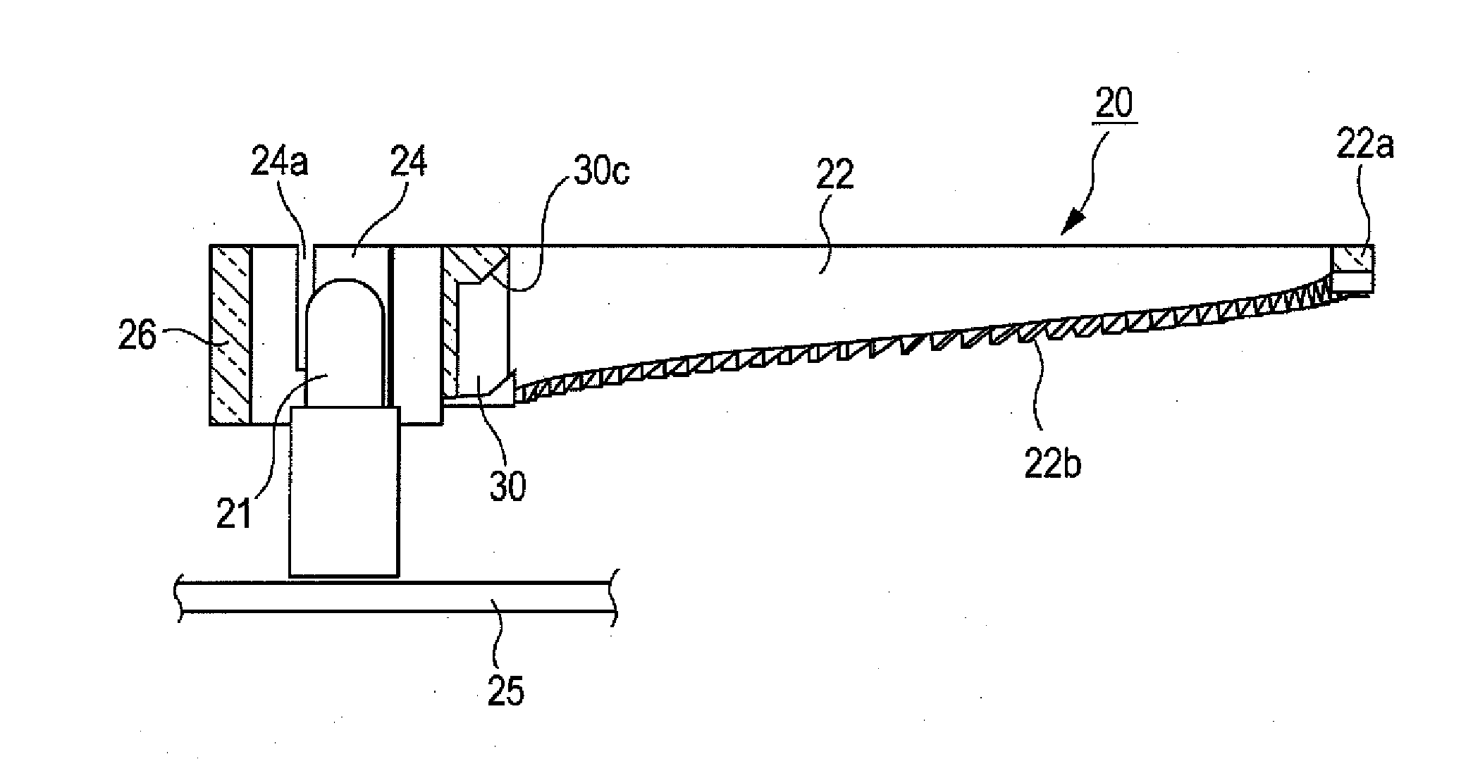
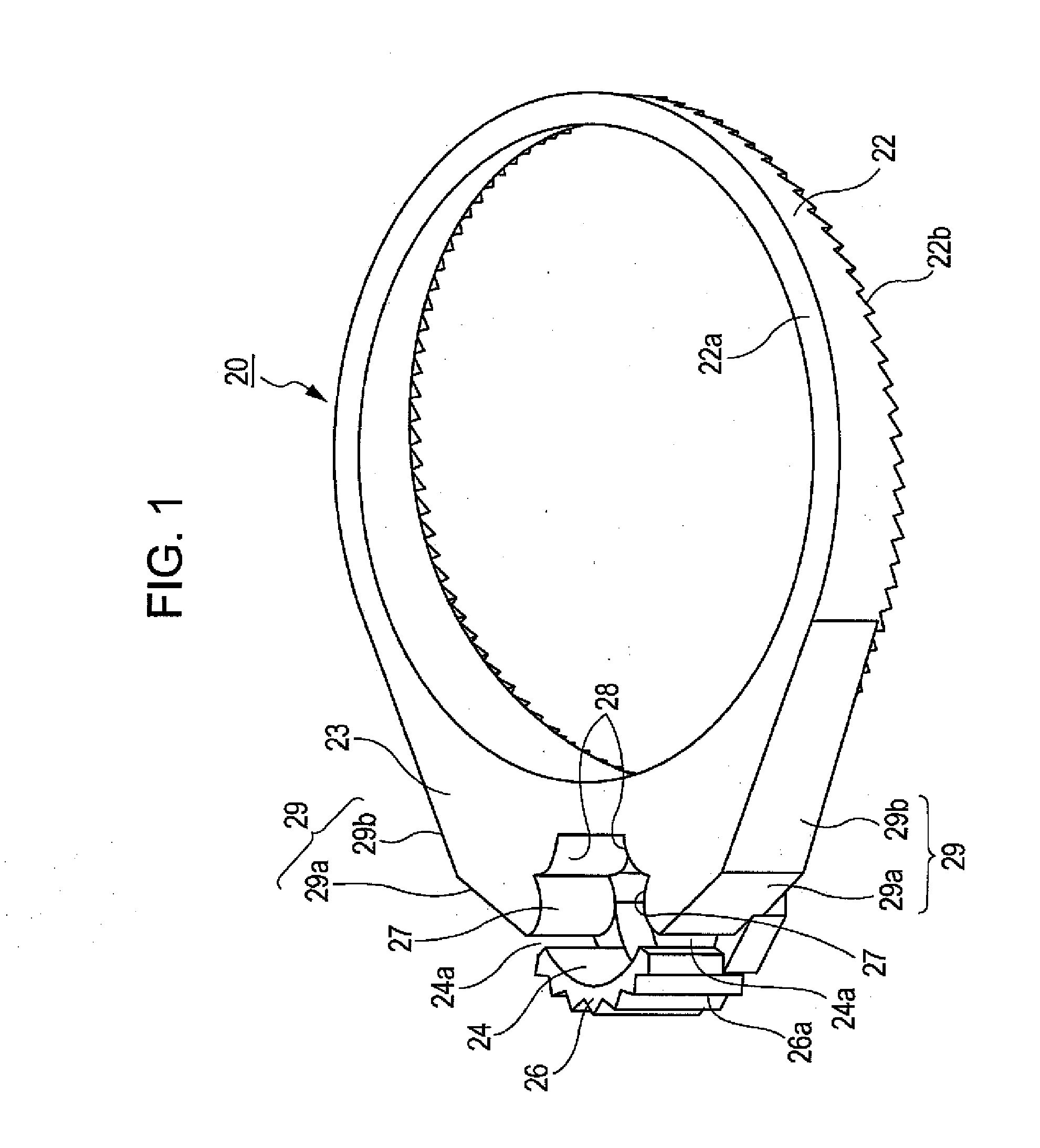
[0041]In one embodiment, as shown in FIG. 1, a surface emitting device includes a light guide 20 and a light source 21. The light guide 20 is molded from a highly light-transmissive material, for example, acrylic resin. The light source 21 emits light into the light guide 20. A lamp is used as the light source 21. The light guide 20 includes a circular portion 22 that curves light and a light entrance portion 23. The light entrance portion 23 is integral with the circular portion 22 and protrudes outward from the outer peripheral surface of the circular portion 22. The circular portion 22 becomes thinner away from the light entrance portion 23. The upper side of the circular portion 22 is a flat emitting surface 22a. The lower side of the circular portion 22 is a serrated reflecting surface 22b.

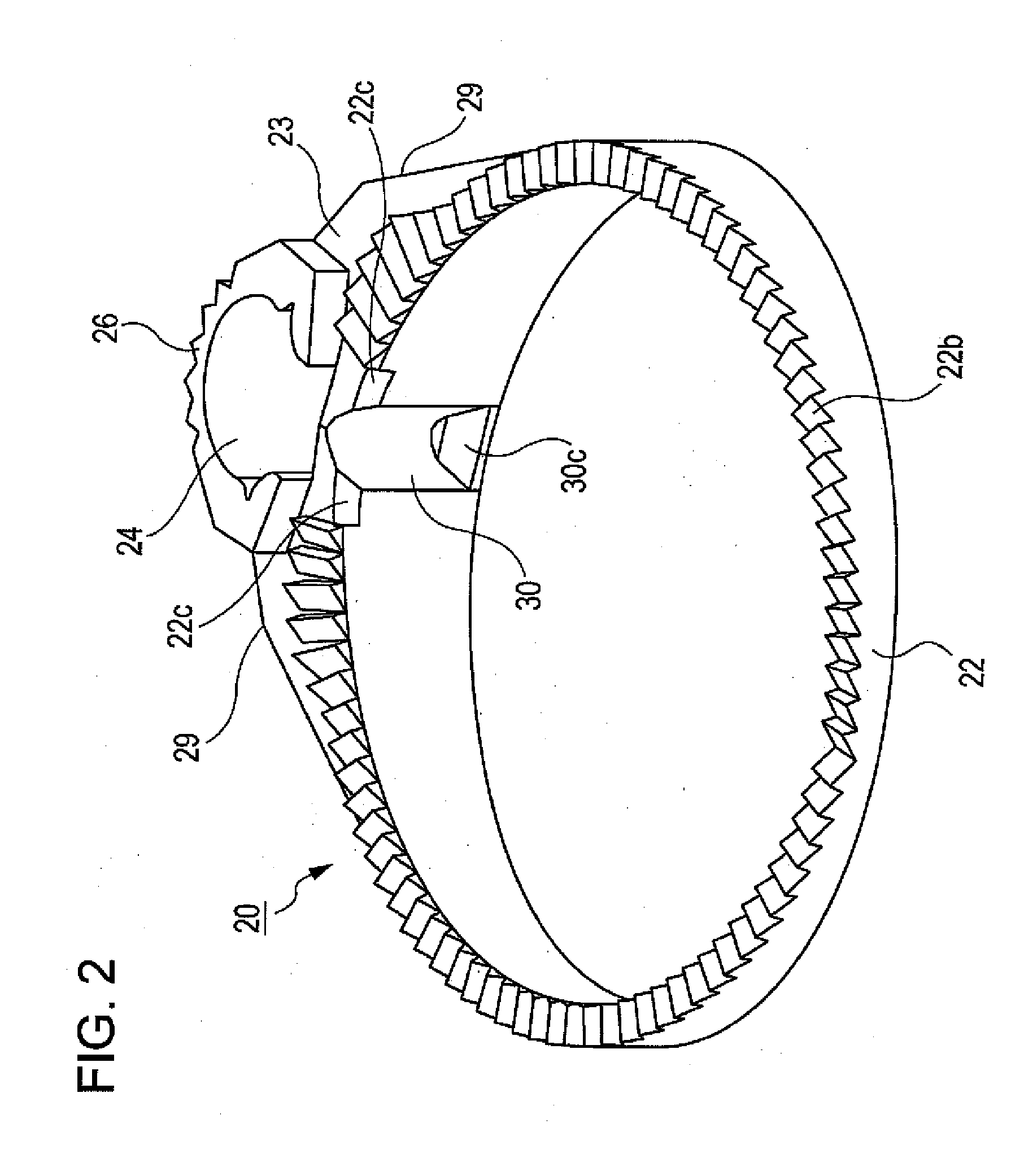
[0042]In one embodiment, as shown in FIG. 2, the serrated reflecting surface 22b has many teeth that extend in the radial direction and that adjoin along the circumferential direction. Light...


PUM


Abstract

A surface emitting device is provided. The surface emitting device includes a light guide and a light source. The light guide includes a circular portion that curves light, and a light entrance portion that protrudes from the outer peripheral surface of the circular portion. The light source emits light toward the light entrance portion. The light source is disposed in a hollow formed in the center of the light entrance portion. The outer wall surface of the light entrance portion has a reflecting portion. The reflecting portion includes first and second reflecting surfaces that adjoin at an obtuse angle. Light of the light source heading from the inner wall surface to the outer wall surface of the light entrance portion is reflected by the reflecting portion so as to head into the circular portion.

Description

[0001]This patent document claims the benefit of Japanese Patent Application No. 2006-003969 filed on Jan. 11, 2006 and Japanese Patent Application No. 2006-003972 filed on Jan. 11, 2006, which are both hereby incorporated by reference.BACKGROUND[0002]1. Field[0003]The present embodiments relate to a surface emitting device.[0004]2. Related Art[0005]Surface emitting devices are generally known in the related art. For example, Japanese Unexamined Patent Application Publication No. 2004-227855 discloses a rotary operating electric component used in car-mounted air conditioning systems and audio systems. The rotary operating electric component includes a rotary knob that is operated by a car occupant and a circular thin plate that is disposed around the knob. The plate has display portions arranged along the circumferential direction. In order to view the rotational operational position of the rotary knob even in the dark, a surface emitting device is widely used.[0006]The surface emit...

Claims


Application Information

Patent Timeline
IPC IPC(8): F21V7/04
CPCG01D11/28G02B6/0038G02B6/0018
Inventor NISHIYAMA, YOSHINORIKOBAYASHI, AYUMU
Owner ALPS ALPINE CO LTD
Why Eureka
Try Eureka