Surface light source and electrically illuminated signboard

a technology of electrical illumination and light source, which is applied in the direction of lighting and heating apparatus, instruments, display means, etc., can solve the problems of inability to achieve perfect uniformity in a surface, inability to obtain light source of a large type, and enlarging of television receivers or the like, so as to improve color rendering properties, uniform brightness, and thin backlight

Inactive Publication Date: 2007-07-12
ZYCC +1
View PDF6 Cites 38 Cited by
  • Summary
  • Abstract
  • Description
  • Claims
  • Application Information

AI Technical Summary

Benefits of technology

[0028]As a result, even in liquid crystal television receivers of a large type, a light source can be obtained in which: a thin backlight with uniform brightness can be realized; the brightness can be controlled for each of surface light source units; the brightness or the like of backlight can be controlled for each of areas; and not only improv

Problems solved by technology

In recent years, liquid crystal display devices are used as display screens, being accompanied with thinning of monitors for television receivers, personal computers or the like, and furthermore the television receivers or the like have a tendency of enlarging.
In the former case, although brightness in almost entire surface can be uniformed by the light guide plate in a liquid crystal panel of a small type having a side of, for example, approximately 50 mm or less, a light source of a large type can not be obtained without arranging a number of the light guide plates because uniformity in a surface can not be achieved perfectly in the liquid crystal display devices having a screen larger than that described above.
Namely, a surface light source of a desired size can not be obtained by arranging (tiling) a number of light guide plates.
Furthermore, there occurs a problem that uniform chromaticity can not be obtained, since chromaticity of each LED varies even among white LEDs and since a distance to the light diffusion member 114 should be larger because lights are not mixed perfectly in case of making white light by mixing colors by using each of LEDs of R, G, and B.
In case of using LEDs for the light sources, there rise same problems as that in backlights for liquid crystal display devices as described above.
Uniform irradiation from an entire surface by diffusing the light in t

Method used


Image

  • Surface light source and electrically illuminated signboard
  • Surface light source and electrically illuminated signboard
  • Surface light source and electrically illuminated signboard

Examples


Embodiment Construction

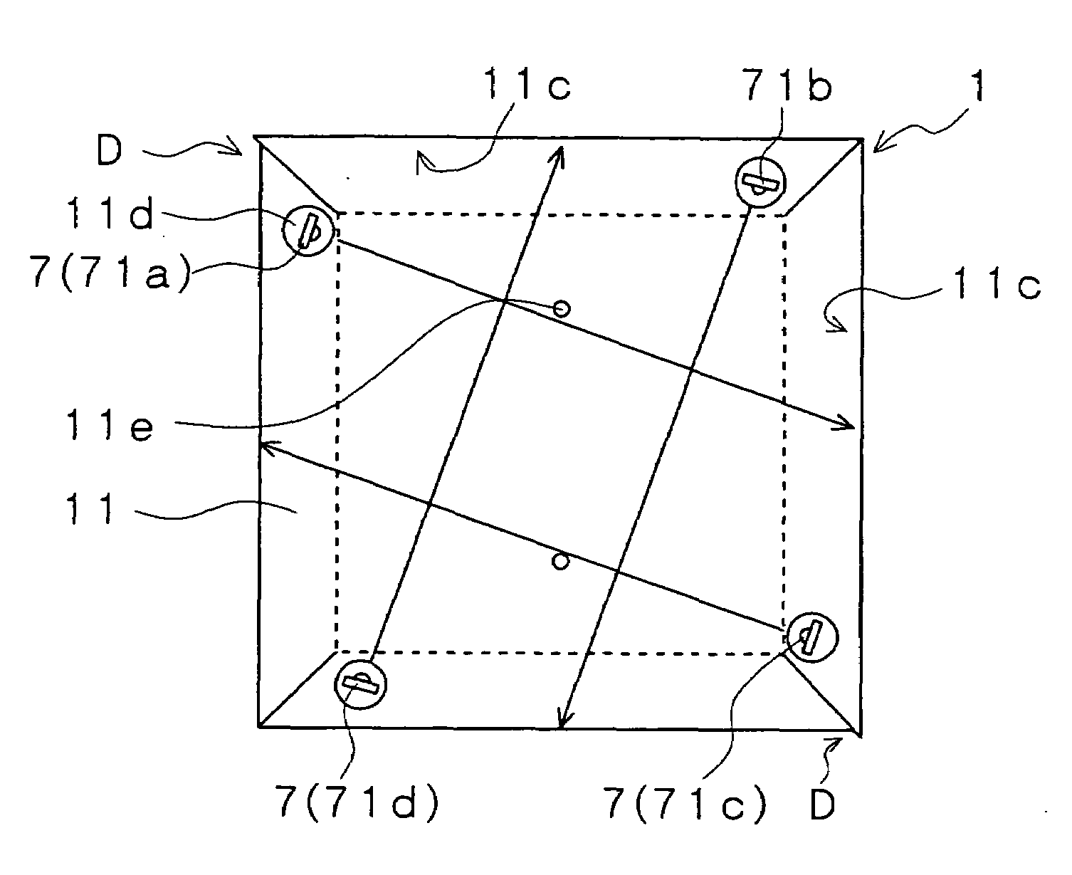
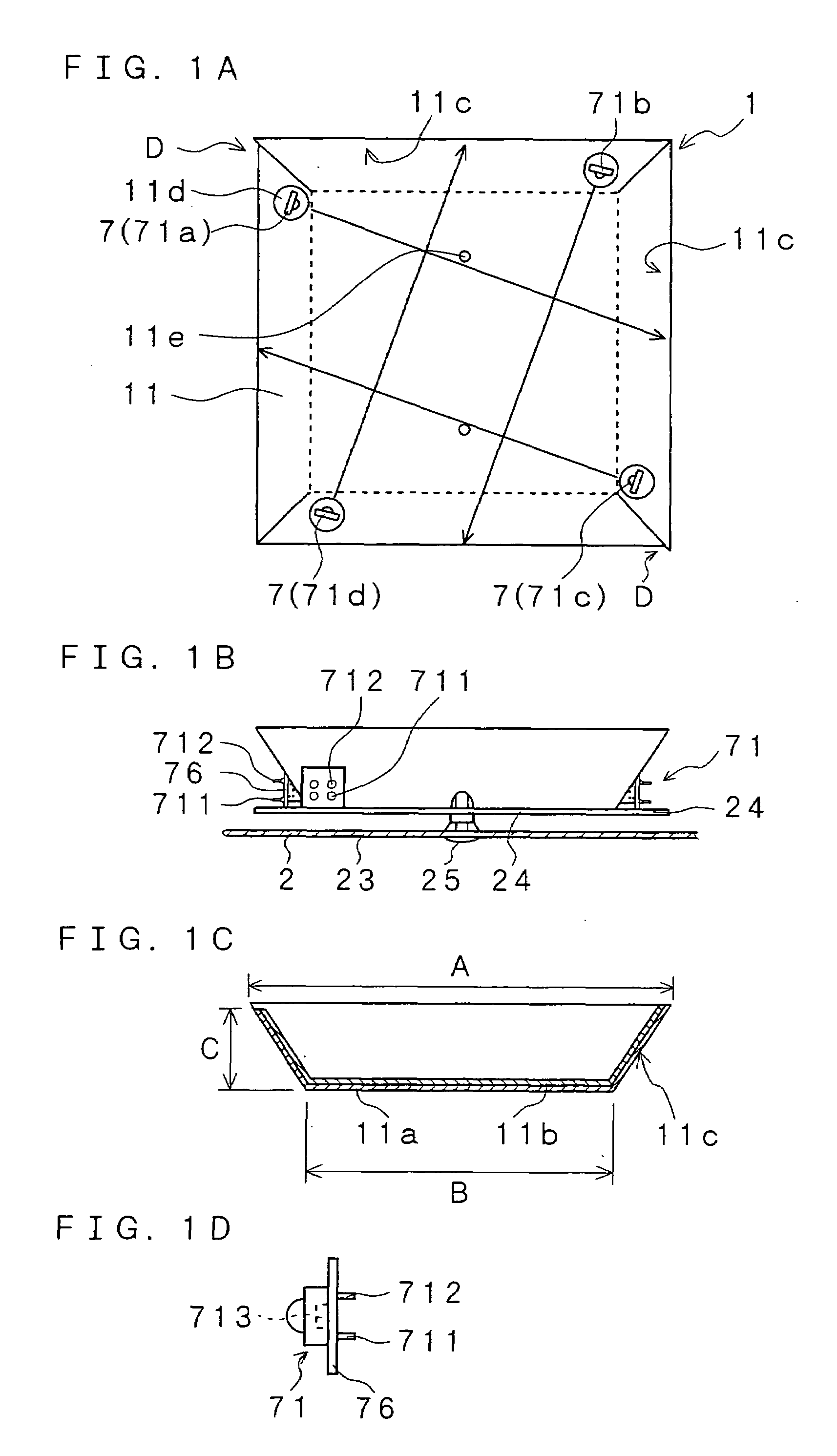
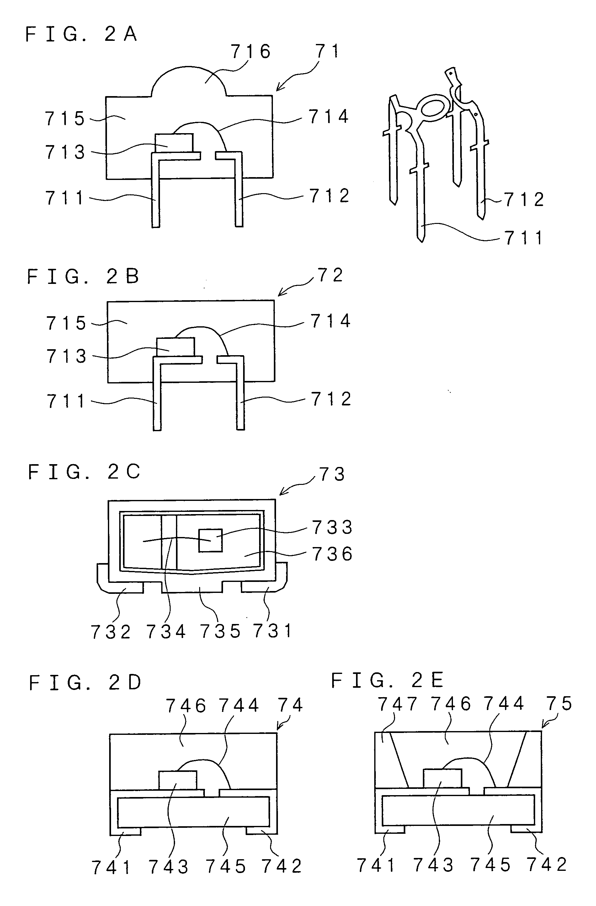
[0043]An explanation will be given below of a surface light source according to the present invention and an electrically illuminated signboard using the same in reference to the drawings. As there are shown in FIGS. 1A to 1D, figures explaining a plan view and a side view of an embodiment of the surface light source unit according to the present invention, a cross-sectional view of the box body and a side view of a light emitting device, the surface light source unit according to the present invention is provided with LEDs 7 of a chip type provided on at least opposite two corners of the bottom surface of the box body 11 of a tray shape so as to irradiate inside of the box body, whose bottom surface is quadrilateral, whose upper side is open, on an inner surface of which a light diffused-reflection member 11b is provided, and whose side walls 11c are inclined outward. Here, a plurality of LEDs 7 (71) are arranged so that a region irradiated by each of the LEDs 7 (71) rotates in a c...


PUM


Abstract

LEDs (7) are arranged on at least opposite two corners of a bottom surface of a box body (11) of a tray shape whose bottom surface is quadrilateral, whose upper side is open, on an inner surface of which a light reflection member (11b) is provided, and whose side walls (11c) are inclined outward, so as to irradiate inside of the box body, wherein a plurality of LEDs (71) are arranged so that a region irradiated by each of the LEDs (71) rotates sequentially in a specific direction (same direction). As a result, there can be obtained a surface light source having high brightness and uniformity in an arbitrary size whether the light source is small or large while using semiconductor light emitting devices (LEDs), and an electrically illuminated signboard using the surface light source, which is thin and capable of uniform display and which operates with low electricity consumption.

Description

FIELD OF THE INVENTION[0001]The present invention relates to a surface light source used as backlights of liquid crystal display devices, illuminations of electrically illuminated signboards, or the like and relates to an electrically illuminated signboard using the same. More particularly, the present invention relates to a surface light source capable of uniforming brightness and chromaticity on its surface, which can be used for backlights of liquid crystal display devices such as television receivers of a thin and large type, or the like, while using semiconductor light emitting devices (LEDs) for light sources, and relates to an electrically illuminated signboard using the same.BACKGROUND OF THE INVENTION[0002]In recent years, liquid crystal display devices are used as display screens, being accompanied with thinning of monitors for television receivers, personal computers or the like, and furthermore the television receivers or the like have a tendency of enlarging. Cold catho...

Claims


Application Information

Patent Timeline
IPC IPC(8): F21V7/04
CPCG02F1/133603G02F1/133611G02F1/133605
Inventor SAKAI, YOSHIHIRO
Owner ZYCC
Why Eureka
Try Eureka