Clock reproducing apparatus

a clock and apparatus technology, applied in the field of clock reproducing apparatus, can solve the problems of inability to use methods, inability to perform well oscillation, and inability to achieve stable oscillation operation, etc., and achieve the effect of stable oscillating operation

Inactive Publication Date: 2007-07-12
YOKOGAWA ELECTRIC CORP
View PDF3 Cites 23 Cited by
  • Summary
  • Abstract
  • Description
  • Claims
  • Application Information

AI Technical Summary

Benefits of technology

[0046] In accordance with the above-described clock reproducing apparatus, the head of the packet as the input data is detected so as to produce the pulse, and then, the gated oscillator can be reset by this pulse, so that this reset operation may contribute the stable oscillating operation.

Problems solved by technology

In the method of using the PLL circuit shown in FIG. 20, such a problem arises that this method cannot be utilized in a case of the burst mode (namely, packet data are intermittently transmitted) and to a signal of 0 / 1 series in which “0” and “1” continues for long time.
However, this clock reproducing method owns the following problem.
That is, in a case of such a high speed communication which is higher than or equal to 10 Gbps, when “0” and “1” are input, oscillation cannot be performed well, and stable operation of the circuit can be hardly realized.

Method used


Image

  • Clock reproducing apparatus
  • Clock reproducing apparatus
  • Clock reproducing apparatus

Examples


first embodiment

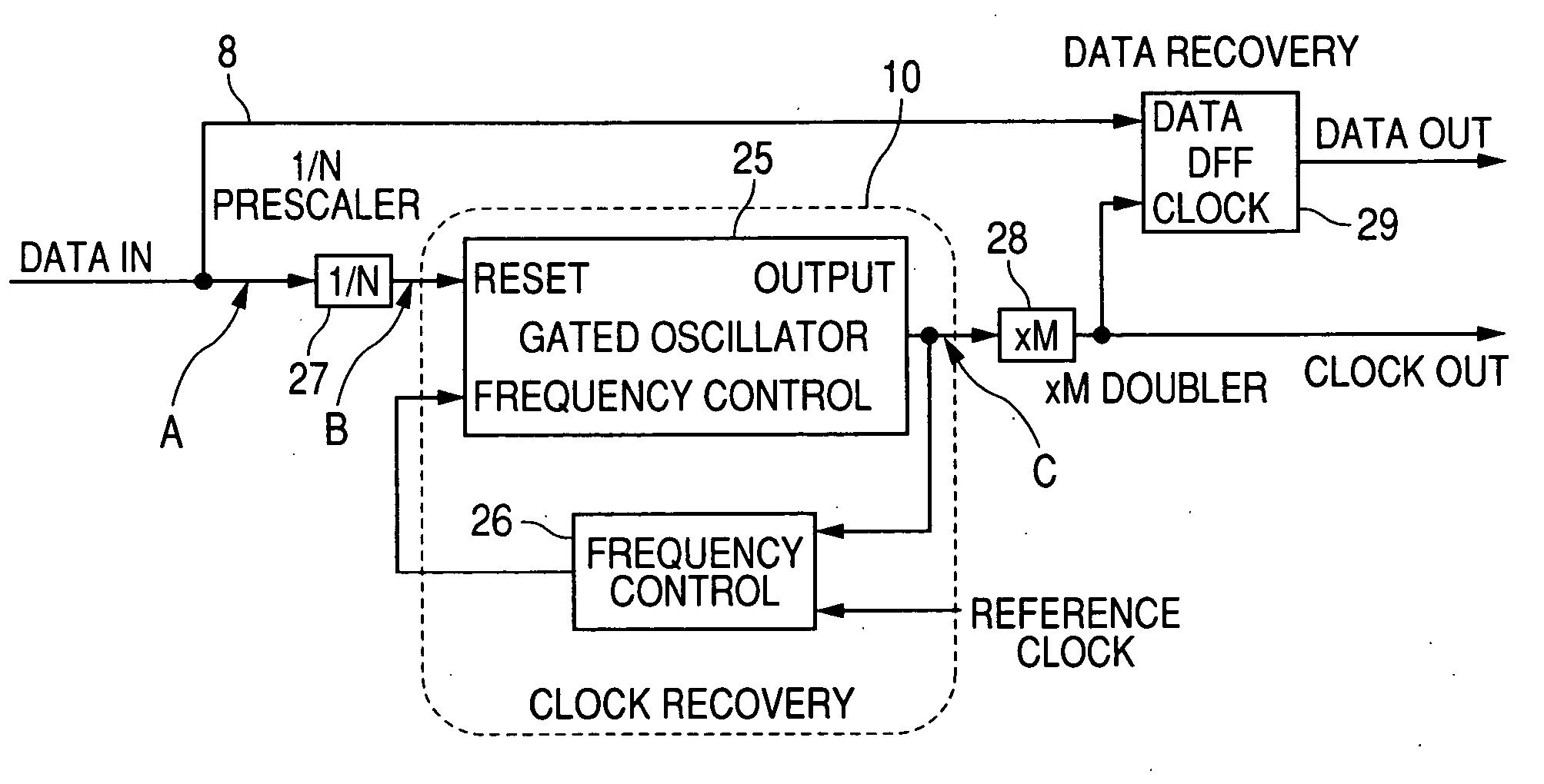
[0070]FIG. 1 is a block diagram for showing a clock reproducing apparatus of the present invention. In this drawing, reference numeral 10 indicates a clock reproducing circuit. The clock reproducing circuit 10 includes a gated oscillator 25, and a frequency control circuit 26 for comparing an output of the gated oscillator 25 with a reference clock, and for supplying a phase control signal for setting a delay time to the gated oscillator 25 based on a comparison result. Reference numeral 27 shows a 1 / N frequency divider or a prescaler for dividing a frequency of input data by 1 / N, and reference numeral 28 indicates an M frequency multiplier or M-doubler for multiplying an output of the clock reproducing circuit 10 by M, and an output of the M frequency multiplier 28 is input to a clock input terminal of a D type flip-flop (will be abbreviated as “DFF” hereinafter) 29. On the other hand, the input data is directly input via a signal line 8 (delay line) to a data input terminal of the...

second embodiment

[0084]FIG. 11 is a block diagram for showing a clock reproducing apparatus according to the present invention. In this drawing, reference numeral 120 shows a pulse forming circuit which receives input data (DATA In) so as to form a pulse from the received input data. Reference numeral 130 represents a clock reproducing circuit including a gated oscillator 131 and a frequency control circuit 132 for comparing an output of the gated oscillator 131 with a reference clock, and for supplying a phase control signal for setting a delay time to the gated oscillator 131 based on a comparison result.

[0085] The pulse forming circuit 120 is a circuit for generating a reset pulse in synchronism with an input signal (data). The clock reproducing circuit 130 is a circuit for reproducing a clock in synchronism with the reset pulse. In the pulse forming circuit 120, reference numeral 125 shows a frequency divider which divides the input signal by 1 / N, and reference numeral 126 represents a capacitor...

third embodiment

[0092]FIG. 14 is a block diagram for showing a first structural example of a clock reproducing apparatus according to the present invention. It should be noted that the same reference numerals shown in FIG. 11 are employed as those for the same circuit elements, and explanation thereof are not repeatedly made. In the drawings, reference numeral 120A shows a pulse forming circuit. This pulse forming circuit 120A forms a reset pulse not by using a differentiating circuit, but by employing an AND circuit. Arrangements of a clock reproducing circuit 130, a frequency multiplier 141, and a DFF 142 are identical to those of FIG. 11. It should also be noted that as a gated oscillator, such a gated oscillator shown in FIG. 22 is employed.

[0093] A description is made of operations of the pulse forming circuit 120A in the circuit arranged in the above-explained manner. In this circuit, reference numeral 125 shows a 1 / N frequency divider. In this case, a ½ frequency dividing operation is repres...


PUM

PropertyMeasurementUnit
frequenciesaaaaaaaaaa

Abstract

A clock reproducing apparatus includes a clock reproducing circuit having: a gated oscillator having an oscillating circuit of two routes; and a frequency control circuit for comparing a phase of an output of the gated oscillator with a phase of a reference clock, and supplying a phase control signal to the gated oscillator based on the comparison result so as to set a delay time, input data is input to a reset input terminal of the gated oscillator, and different route of the two routes of the oscillating circuit operates depending on a case where the input data is “H” and a case where the input data is “L”.

Description

[0001] This application claims foreign priorities based on Japanese Patent application No. 2006-005161, filed Jan. 12, 2006 and Japanese Patent application No. 2006-005162, filed Jan. 12, 2006, the contents of which are incorporated herein by reference in their entireties. BACKGROUND OF THE INVENTION [0002] 1. Field of the Invention [0003] The present invention is related to a clock reproducing apparatus. Recently, in a data transfer field, there is a need for transferring large amounts of data in high speeds. For example, such a method has been increased in which data transfer apparatuses are coupled to each other by employing optical fibers so as to transfer large amounts of data in high speeds. In this sort of transfer method, data transmitted via the optical fibers are converted into electric signals by an optical / electric converter, and thereafter, the data are reproduced. In this sort of technical field, since there are many possibilities that data are transmitted in a burst m...

Claims


Application Information

Patent Timeline
Patent Type & Authority Applications(United States)
IPC IPC(8): G11B7/00
CPCH03K3/0315H03K5/135H03K5/133H04L7/0087H04L7/027H03K2005/00032H04L7/0276
Inventor SUGAWARA, HIROSHISUZUKI, TOSHIMICHIUNEME, SHIGEOIIO, SHINJIMIURA, AKIRAFUJITA, TADASHIGETOYAMA, AKIRAIKEZAWA, KATSUYAKODAKA, HIROTOSHIOKA, SADAHARUSATO, CHIE
Owner YOKOGAWA ELECTRIC CORP
Why Eureka
Try Eureka