
Laser diode controller and method for controlling laser diode by automatic power control circuit

a technology of automatic power control circuit and laser diode, which is applied in the direction of laser details, semiconductor lasers, electrical apparatus, etc., can solve the problems of difficult to compensate for short-period deterioration, greatly deteriorating efficiency, and further deteriorating efficiency

Inactive Publication Date: 2007-07-12
SUMITOMO ELECTRIC IND LTD
View PDF2 Cites 20 Cited by
  • Summary
  • Abstract
  • Description
  • Claims
  • Application Information

AI Technical Summary

Benefits of technology

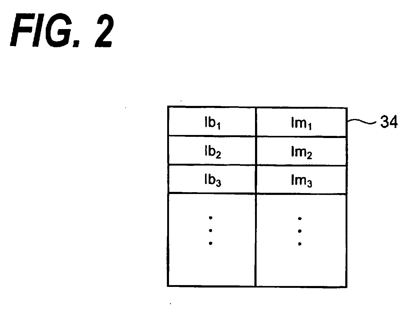
[0007] The first aspect of this invention relates to an automatic power control circuit for stabilizing an optical output power and an extinction ratio of a laser diode by supplying a bias current and a modulation current to the laser diode. The automatic power control circuit includes a first and a second storage, a control processing unit and a signal creating unit. The first storage stores first control data correlating the bias current and the modulation current supplied to the laser diode which simultaneously give a predetermined target power and a predetermined extinction ratio. The central processing unit measures the current optical output power, computes the bias current on the basis of a difference between the target power and the current optical output power, and decides the modulation current corresponding to the bias current obtained by computation according to the first control data. The signal creating unit creates a control signal corresponding to the bias current and modulation current thus decided and supplies it to the laser diode. The second storage stores second control data correlating a temperature of the laser diode and a correction value for the optical output power. The central processing unit, before deciding the bias current, measures the temperature of the laser diode, decides the correction value for the optical output power corresponding to the temperature measured according to the second control data, and corrects the target power on the basis of the correction value. Thereafter, the central processing unit computes the bias current using a difference between the corrected target power and the current optical output power. The bias current may be computed by multiplying the difference between the corrected target power and the current optical output power by a constant. The correction value corresponding to the temperature of the laser diode may be an attenuation of the target power necessary to stabilize the extinction ratio to the temperature of the laser diode at the predetermined value at the temperature.
[0008] The second control data may be a look-up table for storing a plurality of correction values correlated with a plurality of temperatures. The central processing unit, when the current temperature is different from the temperatures set in the look-up table, interpolates the correction values in the look-up table to compute the correction value corresponding to the current temperature.
[0009] Another aspect of this invention relates to a method for controlling a laser diode by supplying a bias current and a modulation current to the laser diode to stabilize an optical output-power and an extinction-ratio. This method includes the following steps of (a) measuring a current temperature of the laser diode; (b) deciding a correction value corresponding to the current temperature; (c) correcting a target power of the laser diode on the basis of the correction value; (d) measuring a current optical output power of the laser diode; (e) deciding the bias current on the basis of a difference between the optical target power and the current optical output power; (f) deciding the modulation current on the basis of the control data defining the relationship between the target power and the extinction ratio which simultaneously satisfies the target power and the extinction ratio; and (g) supplying the bias current and modulation current thus decided to the laser diode. The step (d) may be executed prior to the steps from (a) to (c) of deciding the target power.

Problems solved by technology

However, it is difficult to compensate for short-period deterioration in the luminous efficiency (hereinafter simply referred to as an efficiency) of the LD at a high ambient temperature by the conventional APC circuit.
Specifically, the LD has a temperature characteristic that the threshold current increases at a high temperature and so the efficiency greatly deteriorates.
As a result, positive feedback that the efficiency further deteriorates acts so that the LD becomes gradually incapable of generating a target optical output power (hereinafter simply referred to as a target power).

Method used


Image

  • Laser diode controller and method for controlling laser diode by automatic power control circuit
  • Laser diode controller and method for controlling laser diode by automatic power control circuit
  • Laser diode controller and method for controlling laser diode by automatic power control circuit

Examples


Embodiment Construction

[0018] Now referring to the attached drawings, a detailed explanation will be given of various embodiments of this invention. In the respective drawings, like reference symbols refer to like elements in order to avoid overlaps of explanation.

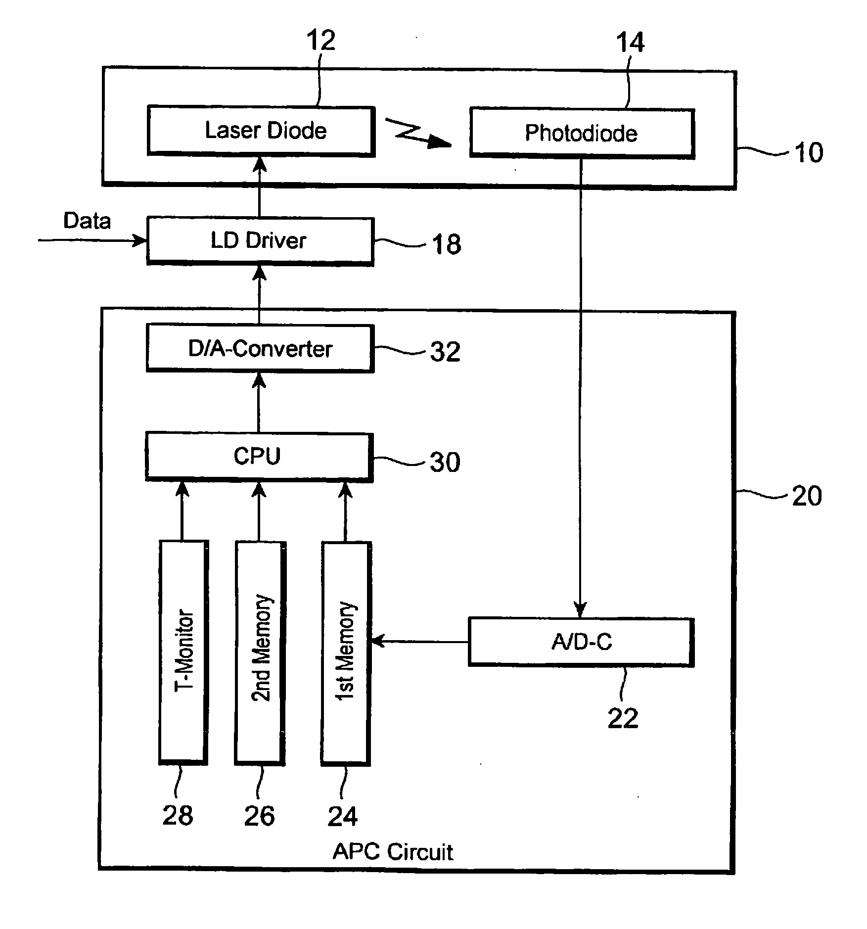
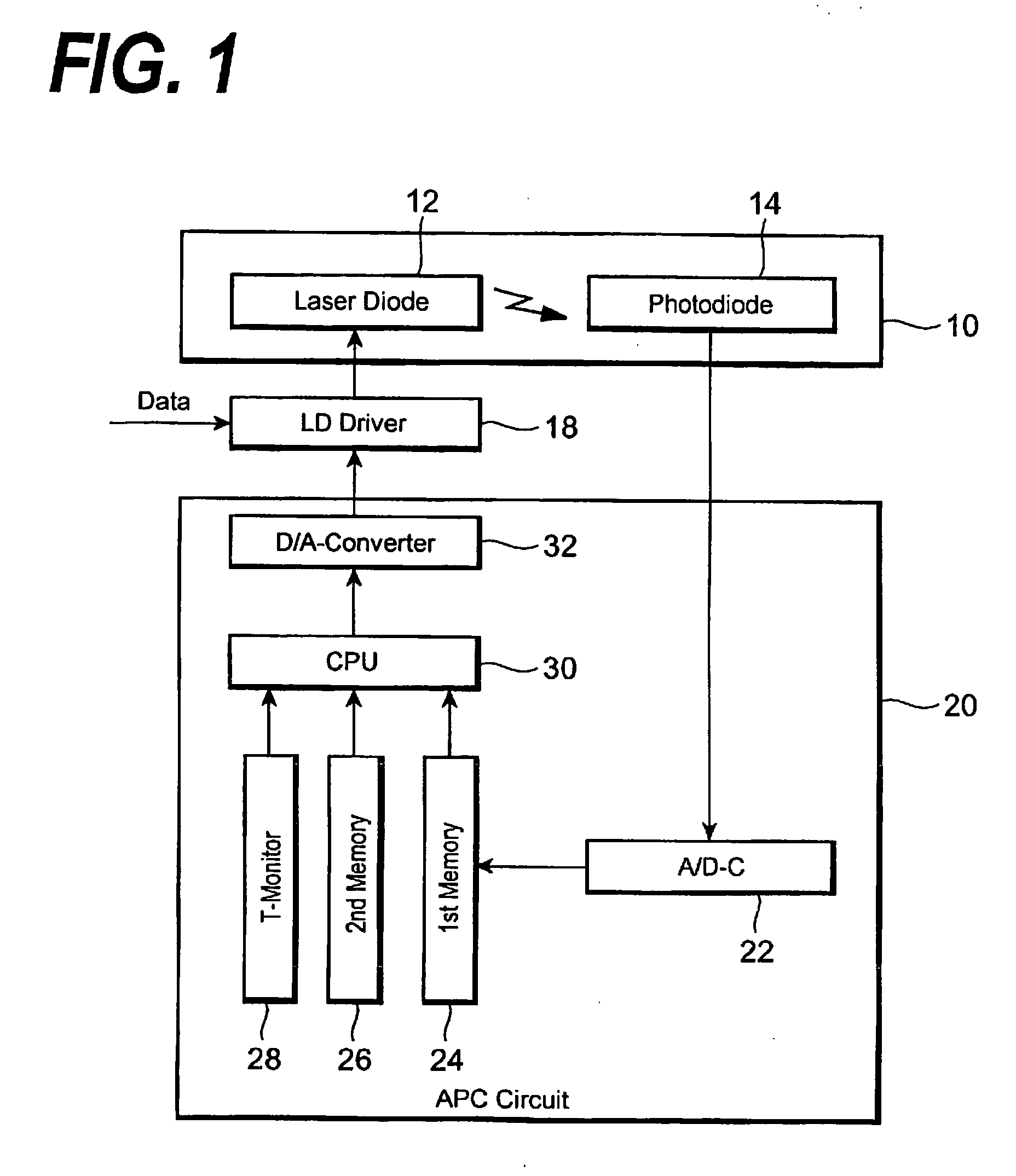
[0019]FIG. 1 is a block diagram schematically showing the configuration of an automatic power control (APC) according to this invention. An APC circuit 20 includes an A / D converter (A / D-C) 22, a first storage (memory) 24, a second storage (memory) 26, a temperature monitor 28, a central processing unit (CPU) 30 and a D / A converter (D / A-C) 32. The APC circuit 20 regulates the bias current (Ib) and modulation current (Im) to be supplied to an LD 12 loaded on a laser module 10, thereby continuing to keep constant the optical output power of the LD 12 and its extinction ratio. The laser module 10 includes a photodiode (PD) 14 for monitoring the optical output power of the LD 12 in addition to the LD 12. An LD driver 18 adds the modulation current I...


PUM


Abstract

This invention provides an automatic power control (APC) circuit for keeping an extinction ratio constant even when the efficiency of a laser diode (LD) deteriorates. The APC circuit according to this invention stores first control data for deciding the relationship between a bias current Ib and a modulation current Im so that the extinction ratio under a certain target power is a predetermined value. A central processing unit (CPU) decides the bias current Ib and modulation current Im on the basis of a current optical output power and the first control data and supplies them to an LD driver. The APC circuit also stores second control data for deciding the correction value for the optical output power corresponding to the temperature of the LD. The CPU acquires the current temperature before deciding the bias current Ib, decides a correction value corresponding to the current temperature according to the second control data, and corrects the target power. Thereafter, the CPU computes the bias current Ib on the basis of the corrected target power.

Description

BACKGROUND OF THE INVENTION [0001] 1. Field of the Invention [0002] This invention relates to an automatic power control circuit for stabilizing an optical output power of a laser diode and a method for controlling the laser diode. [0003] 2. Description of the Related Art [0004] A circuit for regulating the current quantity to be supplied to a laser diode (LD) to stabilize its optical output power is referred to as an automatic power control (APC) circuit. The Japanese Patent Application laid open as JP-H11-135871A discloses an example of the APC circuit. This APC circuit regulates a bias current and a modulation current to be supplied to the LD according to a change in an ambient temperature, thereby stabilizing the optical output power of the LD and its extinction ratio. In addition, the APC circuit disclosed detects secular deterioration of the LD on the basis of the output from a photodiode (PD) for detecting the optical output power of the LD to regulate the bias current. [0005...

Claims


Application Information

Patent Timeline
Patent Type & Authority Applications(United States)
IPC IPC(8): H01S3/13
CPCH01S5/0617H01S5/0683H01S5/06804
Inventor KITAGAWA, KENTAROISHIBASHI, HIROTO
Owner SUMITOMO ELECTRIC IND LTD
Learn More