Interference rejection in telecommunication system

a telecommunication system and interference rejection technology, applied in the field of signal processing in the telecommunication system, can solve the problems of severe inter-symbol interference (isi), computational complexity of the optimum maximum a posteriori probability (map) based sequence estimation for the joint detection of co-channel signals, and reducing the quality of data transmission

Inactive Publication Date: 2007-07-12
NOKIA CORP
View PDF9 Cites 65 Cited by
  • Summary
  • Abstract
  • Description
  • Claims
  • Application Information

AI Technical Summary

Benefits of technology

[0013] In the following, the invention will be described in greater detail with reference to the embodiments and the accompanying drawings, in which
[0014]FIG. 1 shows a prior art interference rejection combining scheme;
[0015]FIG. 2A illustrates a simplified block diagram of a telecommunication system in which embodiments of the invention may be implemented;
[0016]FIG. 2B illustrates an example of an interference suppression scheme in conjunction with diversity combining;
[0017]FIG. 3 illustrates a block diagram of an interference suppression unit according to an embodiment of the invention;
[0018]FIG. 4A illustrates a block diagram of an interference suppression arrangement according to an embodiment of the invention;

Problems solved by technology

Usually, the optimum maximum a posteriori probability (MAP) based sequence estimation for the joint detection of the co-channel signals is computationally too complex.
This causes severe inter-symbol-interference (ISI).
In this case, the gain obtained through the conventional IRC or through a spatio-temporal IRC (ST-IRC) is typically small, resulting in a reduced quality of data transmission.

Method used


Image

  • Interference rejection in telecommunication system
  • Interference rejection in telecommunication system
  • Interference rejection in telecommunication system

Examples


Embodiment Construction

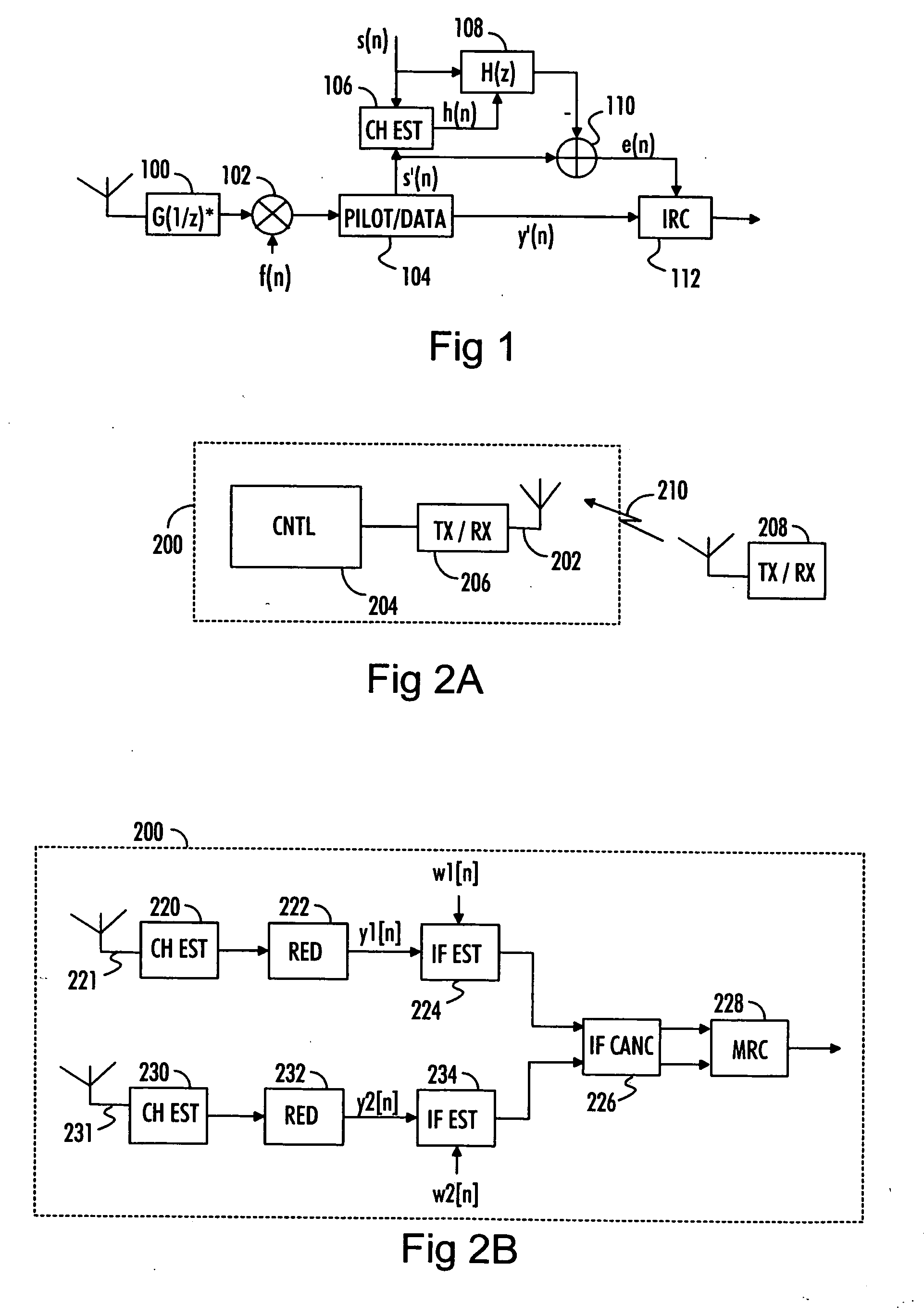
[0021] With reference to FIG. 2A, let us examine an example of a radio receiver 200 in which embodiments of the invention can be implemented. The radio receiver 200 may be a communication device capable of transmitting and receiving radio telecommunication signals or a communication device capable of only receiving such signals. The radio receiver 200 may belong to a telecommunication system and, thus, be a network element, such as a base station of the telecommunication system. The telecommunication system may be, for example, a spread spectrum communication system in which signals are transmitted according to a single carrier transmission technology. The telecommunication system may utilize, for example, code division multiple access (CDMA) and / or frequency division multiple access (FDMA) schemes.

[0022] The radio receiver 200 comprises a communication interface 206 to receive radio signals transmitted over a communication link 210 from a radio transmitter 208, which may be a subs...


PUM


Abstract

An interference suppression scheme is provided for a radio receiver. According to the provided interference suppression scheme, the bandwidth of a received pilot signal and a data signal is divided into a plurality of frequency sub-bands. The pilot signal and the data signal have been transmitted according to single carrier data transmission technology. Interference parameters are calculated for each frequency sub-band separately. Interference suppression may be carried out jointly or separately for each frequency sub-band. After the interference suppression, the frequency sub-bands are combined. A filter bank may be used for dividing the total frequency band into sub-bands.

Description

FIELD [0001] The invention relates generally to signal processing in a telecommunication system and particularly to interference suppression in a radio receiver. BACKGROUND [0002] In a co-channel communication system with frequency reuse, the received signal typically comprises a number of co-channel signals that have propagated through independent multi-path fading channels. Usually, the optimum maximum a posteriori probability (MAP) based sequence estimation for the joint detection of the co-channel signals is computationally too complex. Thus, typically a sub-optimal solution is more advantageous. Such an alternative solution is interference rejection combining (IRC) in which the signals received by the multiple antennas at the receiver are weighted and combined in order to maximize the output signal-to-interference-and-noise ratio (SINR). With IRC, spatial diversity can also be used to reduce the co-channel interference (CCI) at the receiver. [0003] The IRC attempts to suppress ...

Claims


Application Information

Patent Timeline
Patent Type & Authority Applications(United States)
IPC IPC(8): H04B1/00H04B1/18H04B1/10
CPCH04B1/1036H04L25/0328H04L25/03159H04L25/0224H04B1/10H04B7/02H04L1/20
Inventor VAISANEN, PETRIPIIRAINEN, OLLIVAINIKKA, MARKKU
Owner NOKIA CORP
Why Eureka
Try Eureka