
Co-channel handover in a cellular network

Inactive Publication Date: 2007-07-12
TREBLE INVESTMENTS LIABILITY
View PDF22 Cites 43 Cited by
  • Summary
  • Abstract
  • Description
  • Claims
  • Application Information

AI Technical Summary

Benefits of technology

[0010] A first embodiment of the invention concerns a method for transferring service for a mobile station call signal from a first base transceiver station to a second base transceiver station in a wireless mobile telecommunication system, where the first and second base transceiver station include a plurality of common radio frequency channels for traffic communication with mobile stations. The method eliminates the possibility that communications on the second base transceiver station will be initiated on the same frequency as service on the first base transceiver station. Such a handover can result in high levels of interference at the mobile unit and can result in dropped calls.
[0012] If there is at least one available radio frequency channel on the second base station that is exclusive of the current radio channel the mobile is using to communicate with the first base transceiver station, then the an acceptance of the handover request can be communicated from the second base transceiver. This acceptance can be transmitted to a base station controller, a mobile services switching center (MSC), and / or the first base transceiver station. Conversely, a refusal of the handover request can be communicated by the second base transceiver if the set of available radio channels does not include at least one post-handover radio frequency channel exclusive of the current radio channel. In this way, co-channel handovers can be avoided.

Problems solved by technology

Such a handover can result in high levels of interference at the mobile unit and can result in dropped calls.

Method used


Image

  • Co-channel handover in a cellular network
  • Co-channel handover in a cellular network
  • Co-channel handover in a cellular network

Examples


Embodiment Construction

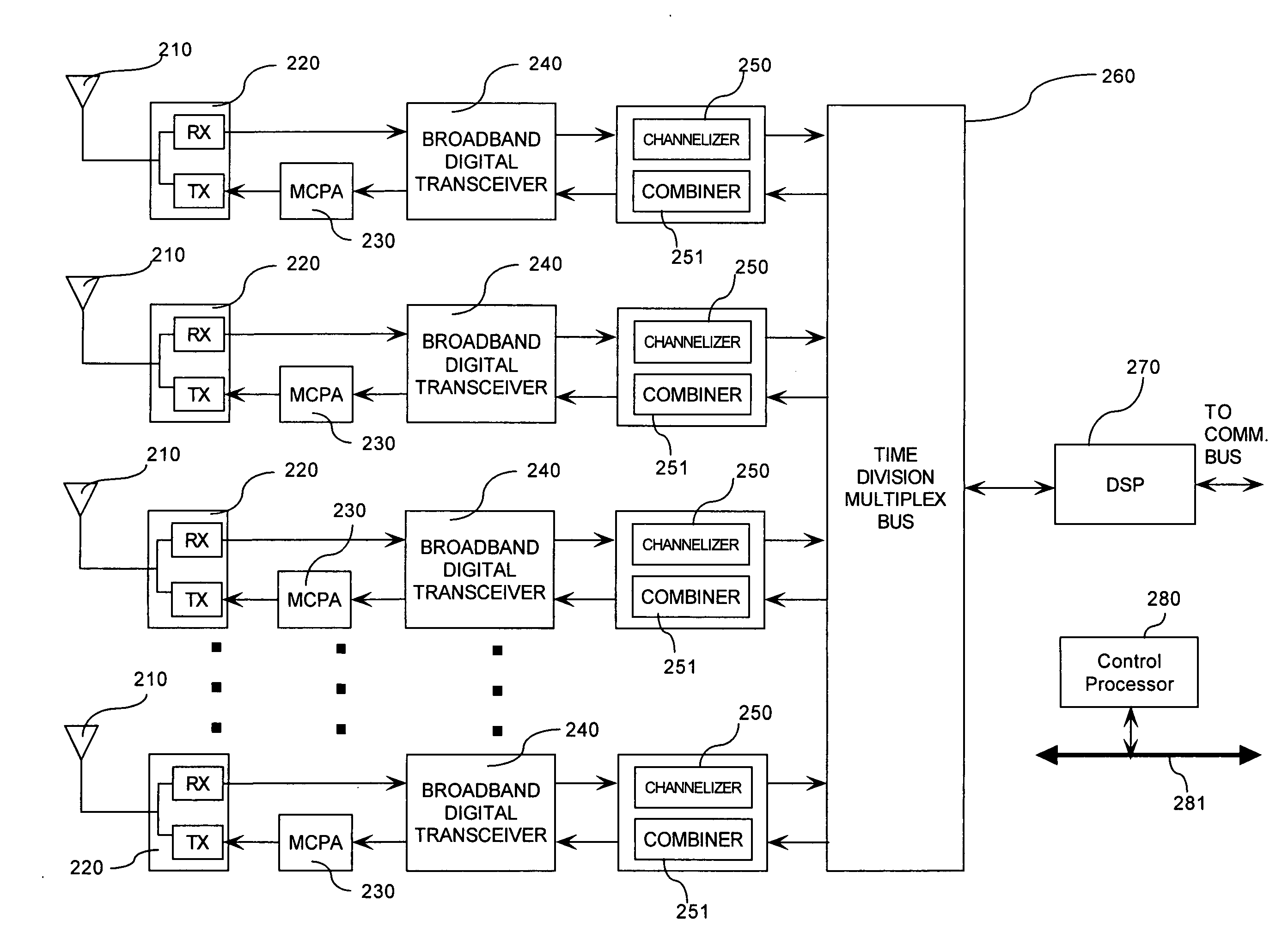
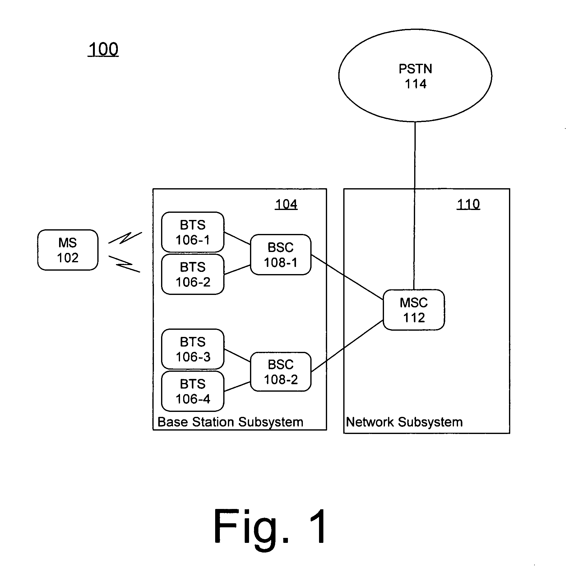
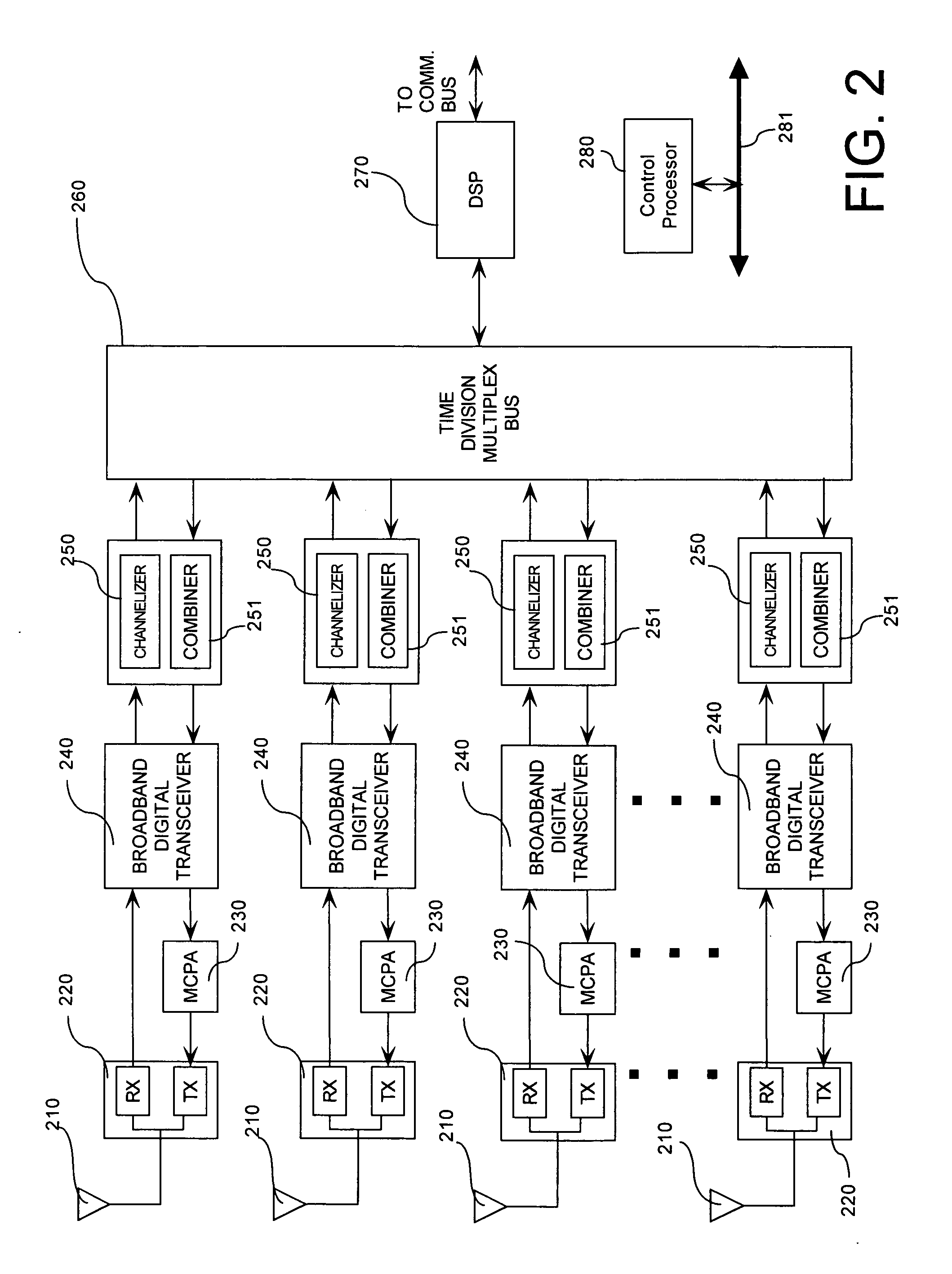
[0033]FIG. 1 shows the architecture of a wireless mobile telecommunication system 100. The architecture shown is for a GSM based system. However, it should be understood that the inventive arrangements are not limited to use in GSM systems. Accordingly, the architecture shown is provided merely by way of example for better understanding the present invention. As shown in FIG. 1, a wireless mobile telecommunication system 100 based on the GSM standard can include a Mobile Station (MS) 102 that includes a Subscriber Identification Module (SIM) and the Mobile Equipment. The system also includes a Base Station Subsystem 104 that controls the radio link with the MS. A Network Subsystem 110 performs switching of calls. The Network Subsystem 110 can switch calls between mobile users, and between mobile users and wired network users. A primary component of the Network Subsystem 110 is the Mobile services Switching Center (MSC) 112. The MSC 112 connects calls within the GSM network and / or ac...


PUM


Abstract

Method for transferring service for a mobile station call signal from a first base transceiver station to a second base transceiver station in a wireless mobile telecommunication system. The first base transceiver station can automatically terminate RF transmissions from the first base transceiver station to the mobile station on a pre-handover RF channel. Thereafter, telecommunication service for the mobile station can be automatically continued using the second base transceiver station. Advantageously, the second base transceiver station can provide the telecommunication service for the mobile station on a post-handover radio frequency channel that is the same as the pre-handover radio frequency channel.

Description

BACKGROUND OF THE INVENTION [0001] 1. Statement of the Technical Field [0002] The inventive arrangements relate to cellular telephone systems and more particularly to handover of mobile stations from one base station to another. [0003] 2. Description of the Related Art [0004] Cellular communication systems generally consist of base stations that transmit and receive radio signals with numerous mobile stations. These communications occur simultaneously on different radio channels of each base station. Conventional base stations commonly employ broad beam antennas to support radio signal coverage over large geographic areas, with each base station intended to cover a different area. The coverage area of a base station will overlap to some extent with the coverage areas of adjacent base stations. These areas of overlap are generally at the outer regions of each base station's coverage areas. [0005] The basic architecture of cellular communication systems and the mobile nature of mobile...

Claims


Application Information

Patent Timeline
IPC IPC(8): H04Q7/20H04W36/08H04W36/18
CPCH04W36/18H04W36/08
Inventor KIENSTRA, KIP W.G. IIIWILLIAMS, TERRY L.
Owner TREBLE INVESTMENTS LIABILITY
Learn More