
Anti-resonance optical fiber temperature detector

An optical fiber temperature and anti-resonance technology, used in thermometers, thermometers with physical/chemical changes, instruments, etc., can solve the problems of long response time, limited measurement position accuracy, and low temperature measurement accuracy, and achieve high temperature sensitivity and transmission. The effect of low latency and short response time

Active Publication Date: 2021-01-29
SOUTH CHINA NORMAL UNIVERSITY
View PDF12 Cites 4 Cited by
  • Summary
  • Abstract
  • Description
  • Claims
  • Application Information

AI Technical Summary

Problems solved by technology

Because the Raman reflection light signal is weak, it usually takes a long response time, and it is difficult to detect the precise position of the temperature change, and the temperature detection accuracy is low; interferometric fiber optic temperature sensors include MZI type and F-P type temperature sensors
Although the sensing accuracy is high, the structure of the sensing element is complex. The MZI type temperature sensor needs two sections of optical fiber as the reference arm and the measuring arm. The F-P type temperature sensor measures the temperature by detecting the reflected light of the end surface coating. The layer is easily polluted by the external environment; the fiber Bragg grating temperature sensor causes the Bragg wavelength drift through the influence of temperature on the grating period and the refractive index of the material, thereby realizing temperature measurement
However, due to the influence of the material parameters of the fiber grating itself, the temperature measurement accuracy is low, and the measurement position accuracy is still limited due to the long measurement element.
[0003] Most of the above-mentioned detectors have large detection elements and a long working distance. Although the detection range is large, it will also lead to the lack of precise detection capabilities for single points, and cannot monitor local temperature changes.
At the same time, the detection sensitivity is limited by the detection principle and the material parameters of the fiber grating itself, which makes it difficult to meet the needs of high-precision temperature detection

Method used


Image

  • Anti-resonance optical fiber temperature detector
  • Anti-resonance optical fiber temperature detector
  • Anti-resonance optical fiber temperature detector

Examples


Embodiment Construction

[0026] This part will describe the specific embodiment of the present invention in detail, and the preferred embodiment of the present invention is shown in the accompanying drawings. Each technical feature and overall technical solution of the invention, but it should not be understood as a limitation on the protection scope of the present invention.

[0027] In the description of the present invention, it should be understood that the orientation descriptions, such as up, down, front, back, left, right, etc. indicated orientations or positional relationships are based on the orientations or positional relationships shown in the drawings, and are only In order to facilitate the description of the present invention and simplify the description, it does not indicate or imply that the device or element referred to must have a specific orientation, be constructed and operated in a specific orientation, and thus should not be construed as limiting the present invention.

[0028] I...


PUM

PropertyMeasurementUnit
lengthaaaaaaaaaa
lengthaaaaaaaaaa

Abstract

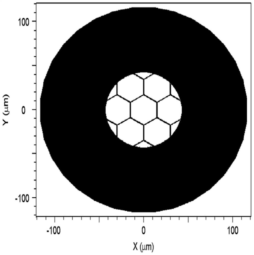
The invention discloses an anti-resonance optical fiber temperature detector which comprises an anti-resonance optical fiber. One end of the anti-resonance optical fiber is connected with a beam expanding optical fiber, and the other end of the anti-resonance optical fiber is connected with a coupling optical fiber; one end of the beam expanding optical fiber is connected with the anti-resonance optical fiber, and the other end is connected with an uplink transmission optical fiber; one end of the uplink transmission optical fiber is connected with the beam expanding optical fiber, and the other end of the uplink transmission optical fiber is connected with an optical fiber light source; one end of the coupling optical fiber is connected with the anti-resonance optical fiber, and the otherend is connected with a downlink transmission optical fiber; and one end of the downlink transmission optical fiber is connected with the coupling optical fiber, and the other end is connected with an optical fiber spectrometer. Due to a fact that a silicon dioxide material is sensitive to a temperature, the temperature influences an optical path difference of the coherent light beams, and interference fringes read out by the optical fiber spectrometer change along with the temperature change of the anti-resonance optical fiber. By monitoring the movement of the fringes, the high-precision temperature monitoring of the anti-resonance optical fiber can be realized. Benefited from optimized device parameters and relatively high interference series, an anti-resonance optical fiber temperature detector has relatively high temperature detection sensitivity.

Description

technical field [0001] The invention relates to the technical field of photodetection devices, in particular to an anti-resonance optical fiber temperature detector. Background technique [0002] Currently commercial fiber optic temperature detectors include distributed fiber optic temperature sensors, interferometric fiber optic temperature sensors, and fiber optic Bragg grating temperature sensors. The distributed optical fiber temperature sensor uses OTDR technology to detect Raman scattered light and realize continuous and real-time temperature measurement in a large spatial range. Due to the weak Raman reflected light signal, it usually takes a long response time, and it is difficult to detect the precise position of temperature change, and the temperature detection accuracy is low; interferometric fiber optic temperature sensors include MZI type and F-P type temperature sensors. Although the sensing accuracy is high, the structure of the sensing element is complex. Th...

Claims


Application Information

Patent Timeline
Patent Type & Authority Applications(China)
IPC IPC(8): G01K11/32
CPCG01K11/32
Inventor 冯建勋黄旭光周桂耀
Owner SOUTH CHINA NORMAL UNIVERSITY
Learn More