
Stretch Pal Exercise Set

Inactive Publication Date: 2007-07-12
TRANCART JEROME +1
View PDF15 Cites 27 Cited by
  • Summary
  • Abstract
  • Description
  • Claims
  • Application Information

AI Technical Summary

Benefits of technology

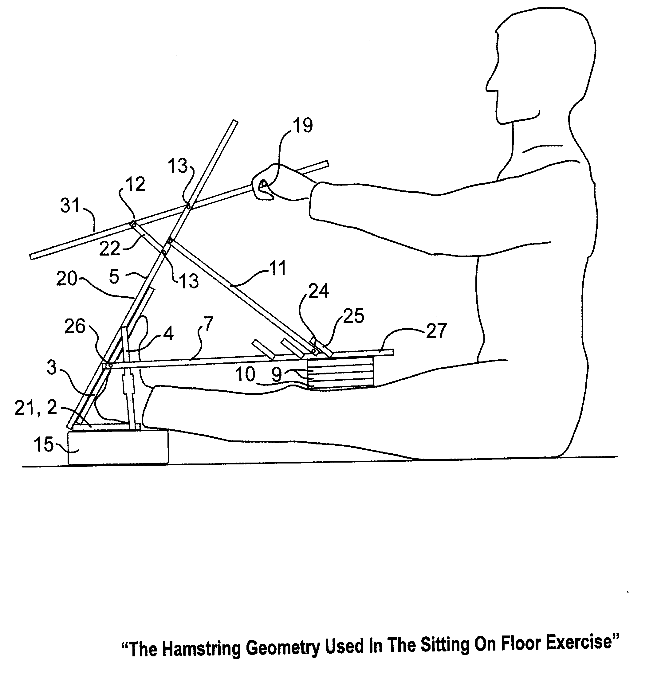
[0009] A second probable arrangement is the Hamstring geometry. Using this exercise geometry, pads press backwards against the knee while the foot cradle holds the ankle in a fixed position. The amount of pressure on the leg is determined by the user pulling on a lever arm which extends at an obtuse angle to the knee pad. Again, an adjustable hand grasp placement permits the progression to a larger lever torque to increase the knee pressure in opposition to the static ankle position. This may be continued to the desired level of Hamstring stretch and then the other leg may be similarly exercised. According to the electron of the user, this may be most easily done with the user sitting in a vertical position or, if he needs his back supported, the user may lie on the floor in a horizontal position. Minor modifications of the basic Hamstring geometry are possible by simple permutations of kit components which will accommodate the various positions of the user as well as his size and build.
[0018] Another object of the invention is to produce a low cost, light, compact, mobile exercise device for athletes, dancers and those general consumers needing simple physical therapy muscle stretching exercises.

Problems solved by technology

Too often, such exercise machines are limited in use and geometric layout or bulky and not very portable.
These are often bulky, heavy and require special placement and supervision.
A danger exists in these machines because of the potential overpowering of the user by the driving energy source.
A hazard exists in these devices if a moving component slips or is maladjusted to an unacceptable limit.
The simpler static devices (U.S. Pat. No. 4,573,678; Lamb; Mar. 4, 1986: U.S. Pat. No. 6,244,992B1; James; Jun. 12, 2001) are very limited to the exercises to be performed.
Some of the other multiple exercise machines are divided up into stations (U.S. Pat. No. 6,228,005 & U.S. Pat. No. 6,413,198B1; Gray; May 8, 2001 &Jul. 2, 2002) and are quite bulky and complex.

Method used


Image

  • Stretch Pal Exercise Set
  • Stretch Pal Exercise Set
  • Stretch Pal Exercise Set

Examples


Embodiment Construction

[0033] Reference is hereafter made to the attached detailed drawing figures which illustrate and clarify the elements of the embodiment.

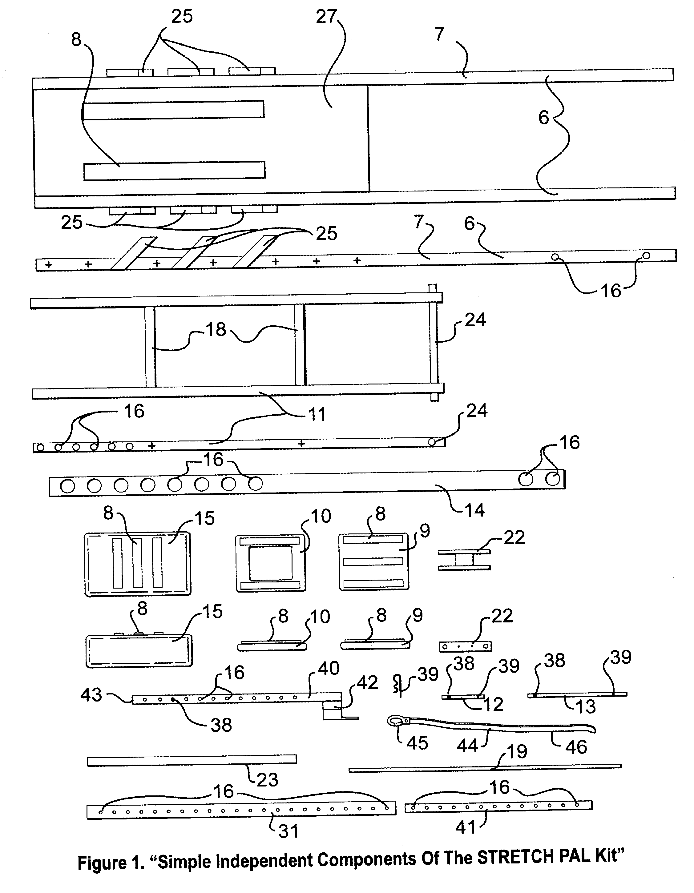
[0034]FIG. 1. “Simple Independent Components Of The STRETCH PAL Kit”

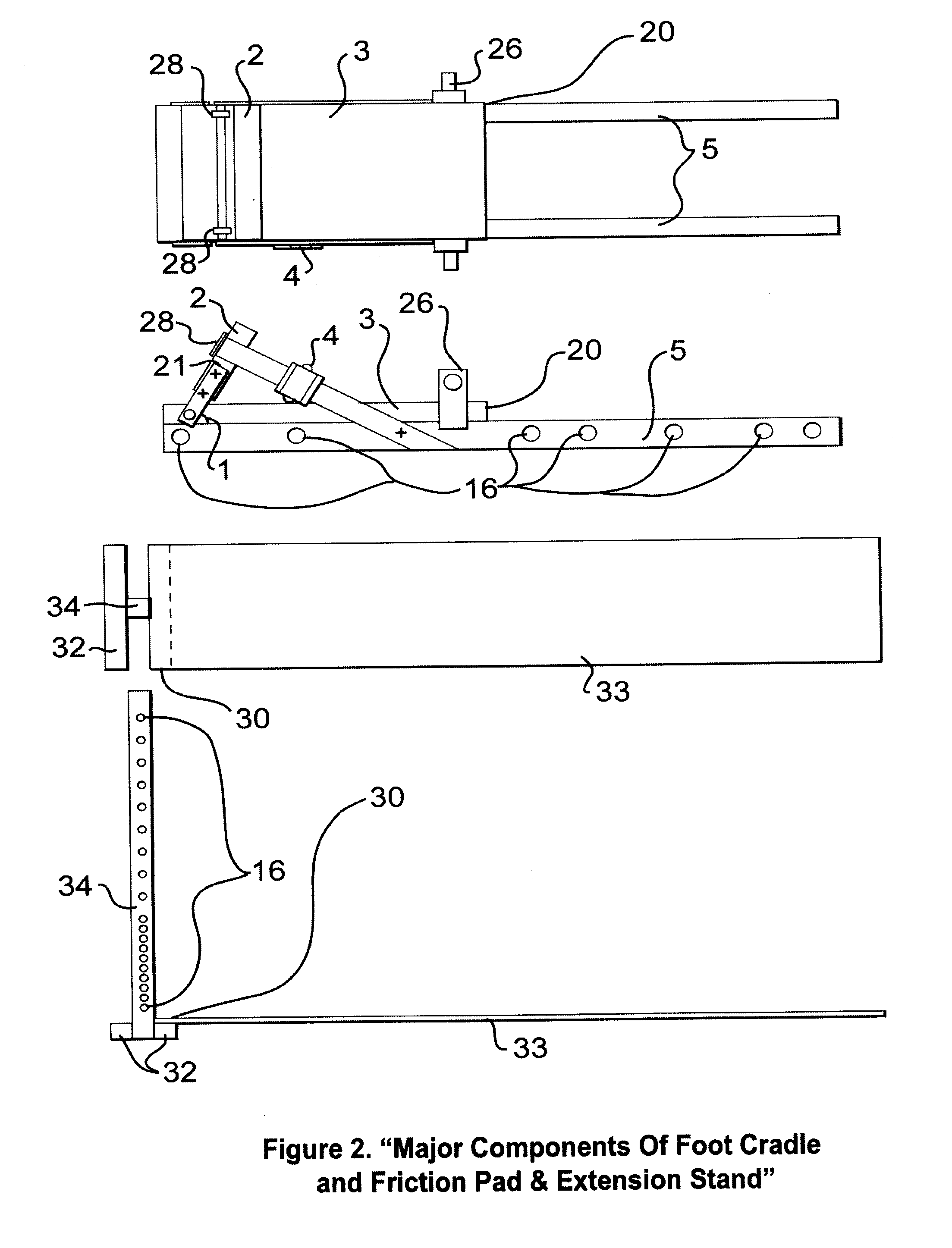
[0035] Each of the aforementioned exercise geometries are generally implemented from the combined assembly of the individual simple components of FIG. 1 with the major components of FIG. 2 of the STRETCH PAL kit. For sake of convenience, the diagrams are not shown to any common scale.

[0036] There are three (3) Pads 9 components include in the kit. One Pad 9 component is shown here in plan and elevation profiles. Each pad has cooperative tacking means 8 attached so it can be adhered to other components to size and adjust the particular exercise geometry to the needs of the user.

[0037] There are available two (2) Frame Pads 10 in the current embodiment of the kit. One Frame Pad 10 is shown here in plan and elevation profiles which have the same overall dimensions as the Pads 9, but...


PUM


Abstract

The invention comprises a versatile compact kit of cooperatively fitting components to be assembled into several geometries of devices capable of being used for the holistic flexion exercise of several muscle groups of the lower torso such as the Achilles tendon, Calf muscles, Hamstrings, Adductor and Lower Back muscles for individual users of different requirements and physical stature.

Description

BACKGROUND OF THE INVENTION [0001] The BACKGROUND OF THE INVENTION is based on the Field and Prior Art as follows: [0002] 1. Field of the Invention [0003] The present invention relates to versatile and collapsible personal exercise equipment intended for the flexion of a variety of muscles in the lower torso. Each configuration is assembled from a kit of cooperating components into several geometries for the flexion exercise of muscle groups of the lower torso. [0004] 2. Discussion of Prior Art [0005] There are a variety of muscles that need stretching exercises to avoid injury in many sports, dancing and athletic activities as well as to alleviate strain problems as part of a regimen of physical therapy. Generally athletes and dancers are trained as to proper exercises and patients in the course of physical therapy are under the supervision of appropriate medical practitioners. Too often, such exercise machines are limited in use and geometric layout or bulky and not very portable....

Claims


Application Information

Patent Timeline
IPC IPC(8): A63B23/08A63B21/06
CPCA61H1/0237A61H2001/0207A61H2201/0161A61H2203/0406A61H2203/0437A63B2210/50A63B2023/006A63B2208/0204A63B2208/0238A63B2208/0247A61H2203/045Y10S482/907
Inventor TRANCART, JEROMETRANCART, JANA
Owner TRANCART JEROME
Learn More