Ocean energy harvesting system

a technology of ocean energy and energy harvesting, applied in the direction of mechanical equipment, machines/engines, electric generator control, etc., can solve the problems of large installation and operating costs, large complexity, and inability to meet the needs of large-scale operation, so as to improve system performance, minimize time and cost, and operate efficiently

Active Publication Date: 2007-07-19
MIGHTY WAVES ENERGY
View PDF4 Cites 8 Cited by
  • Summary
  • Abstract
  • Description
  • Claims
  • Application Information

AI Technical Summary

Benefits of technology

[0022]It is an object of the present invention to effectively capture energy whether near the shore or offshore.
[0034]It is an object of the present invention to minimize environmental impacts including risk to fish or wildlife, damage to the ocean floor, and aesthetic changes to the beach and waterfront.

Problems solved by technology

Many of these have been tested and some operated at sea, but none have resulted in large scale, cost-effective wave energy capture and hence lack commercial viability.
The shortfalls of prior concepts consistently fall into several categories; they are point absorbers and capture a small amount of energy, they rely primarily on the rise and fall of the waves and miss the horizontal energy component of the waves and current, they do not effectively account for tidal motion, they place precision generating equipment in the corrosive salt water environment, their complexity drives large installation and operating costs, and they are vulnerable to severe weather.
These factors combine to render proposed systems inefficient in the capture of wave energy.
This is a point absorber, does not optimally adjust with the tidal shifts, and captures energy only from the incoming action of the wave.
Energy is lost repositioning the boom, the unit does not adjust for tidal shifts, and the conversion device requires pumped intermediate energy storage.
This design is a point absorber requiring a large number of devices for substantial energy capture, relies primarily on the rise and fall of the waves, does not adjust efficiently to tidal shifts, and requires intermediate energy storage.
This approach is a point absorber, limited to energy capture in one relatively small location, and requiring many such devices to be installed to generate substantial energy.
The design is a point absorber, requiring a large number of similar devices to capture substantial energy, and there is no mechanism to account for tidal shift.
This design is a point absorber, places precision equipment under the ocean, requires intermediate pumped storage of energy, and is vulnerable to severe weather.
While the paddles are placed on a horizontal boom, energy is captured at only one point and ocean testing has shown that the disclosed configuration will drive the paddles to float to the very top of the wave and thereby miss most of the available energy.
The system requires intermediate pumped storage and a multi-tiered structure that will be costly and vulnerable to severe weather.
The means for adjusting for tidal shift reduces the overall efficiency of the system at lower water levels.
The design will miss substantial amounts of available energy and does not appear to optimally adjust for tidal variations.
This is a point absorber, not designed to the shape of the waves, and will require many devices to capture a large amount of energy.
Rotation of the arm will cause the device to rise up out of the water and while offering a means to return to the original position, it will miss a substantial amount of energy as the arm elevates.
As demonstrated by the above references, known devices suffer from similar problematic issues.
Ocean waves represent a very attractive renewable energy resource; however, the waves present an unpredictable, asynchronous source that has resulted in the limited utility and application of existing concepts.
Prior designs were not optimized for the shape of the waves as they pass through the ocean.

Method used


Image

  • Ocean energy harvesting system
  • Ocean energy harvesting system
  • Ocean energy harvesting system

Examples


Embodiment Construction

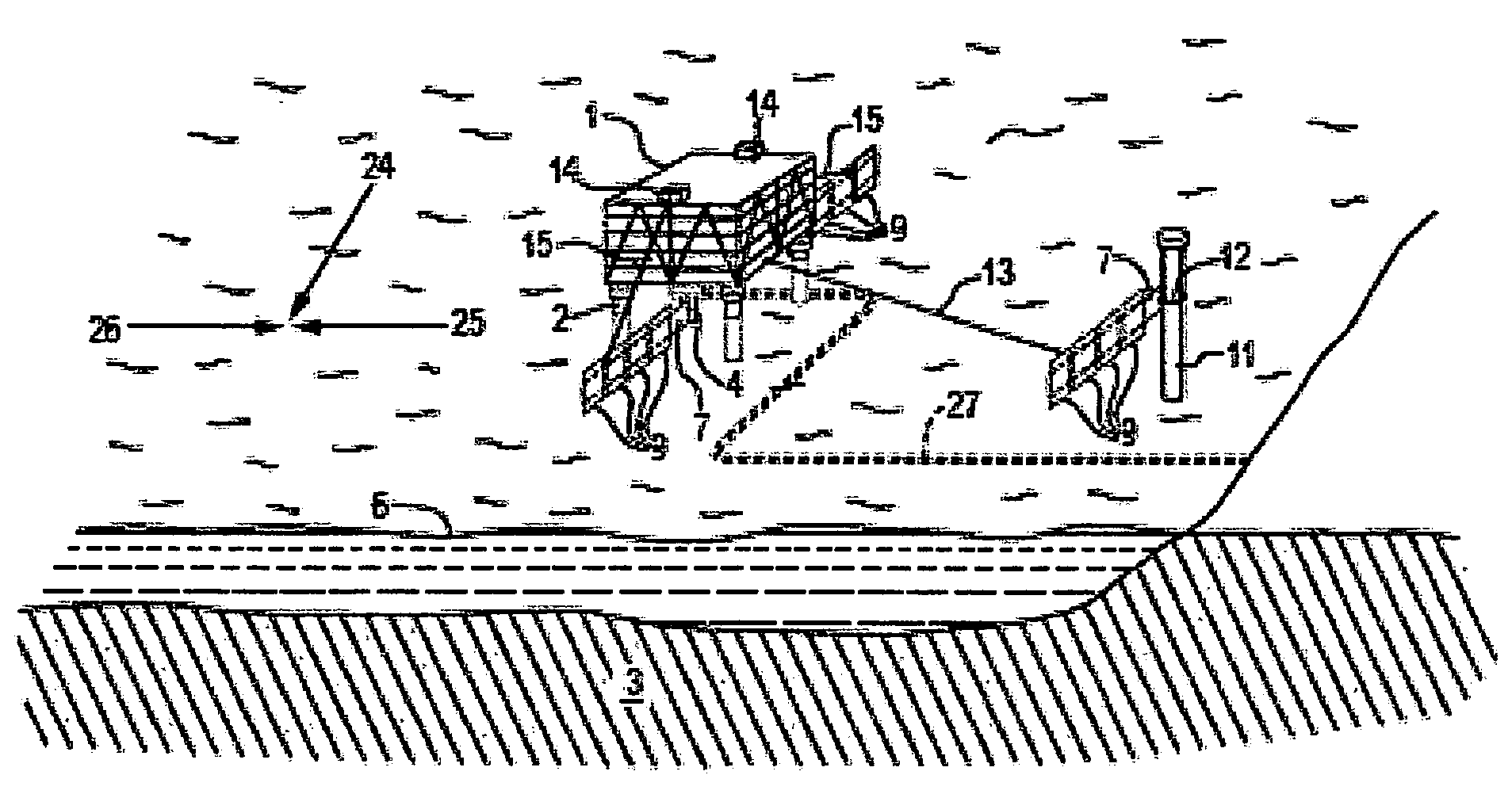
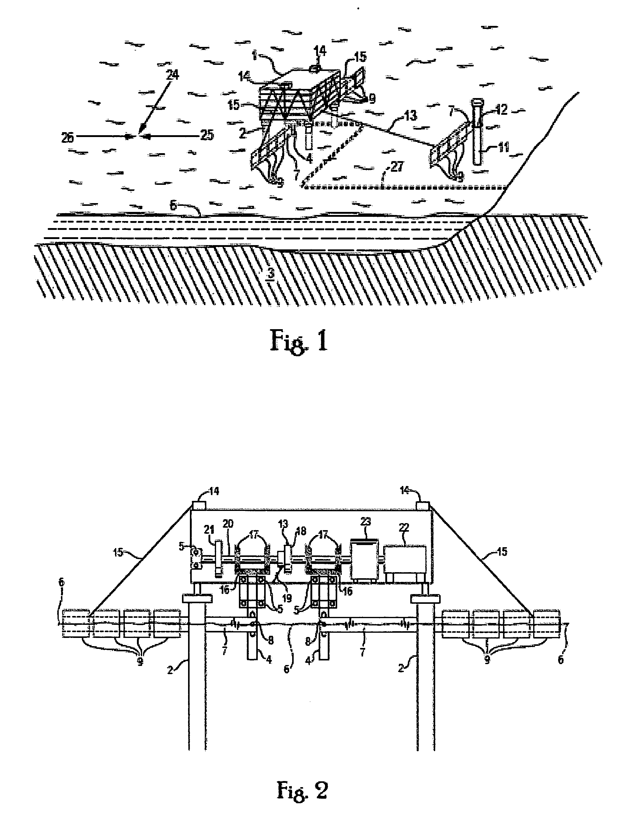
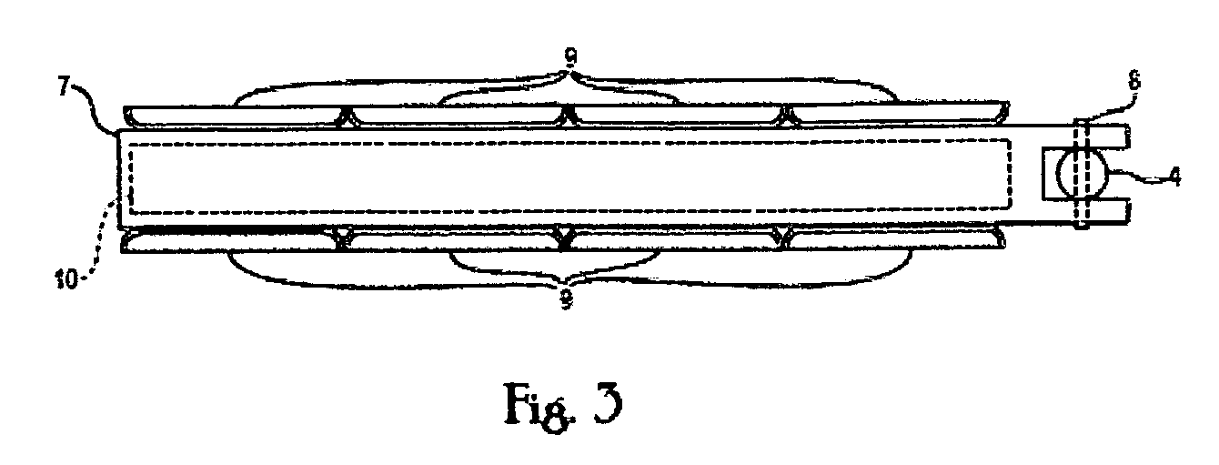
[0066]Referring now to the drawings in greater detail, FIG. 1 shows the wave energy harvesting system of the present invention that involves placing a generator platform 1 near or above the ocean environment using generator platform supports 2 that are either embedded or anchored to the ocean floor 3. The generator platform 1 has a rotational shaft 4 mounted inside using rotational shaft bearings 5. The rotational shaft 4 extends below the floor of the generator platform 1 and down below the water level 6 at low tide. Attached to the rotational shafts 4 are structural members 7 that extend from underneath the generator platform 1 a significant distance into the ocean wave environment. Momentum absorbers 9 are attached to the structural members 7 and create a large cross-section for harvesting wave and current energy. Flotation material 10 is embedded inside the structural members 7 to keep the structural members floating on the water level 6, with the momentum absorbers 9 extending ...


PUM


Abstract

An ocean energy harvesting system utilizes horizontal structural members that rotate in response to wave motion. The structural members are designed to capture energy in a line array that replicates the shape of the waves as they pass through the ocean. A generator platform is placed in the ocean environment or on the shore, and the structural members rotate under the platform or around a pivot post placed in proximity to the platform. The rotation drives a generator shaft due to direct attachment to the structural member or from a cable attached to a structural member some distance from the platform. The structural members can be of substantial length depending on the prevailing wave conditions at the site and the desired amount of energy capture. The system adjusts to differing water levels due to tidal shifts.

Description

[0001]This application claims the benefit under 35 U.S.C. §119(e) of U.S. provisional patent application No. 60 / 758,972, filed Jan. 17, 2006 and entitled Ocean energy harvesting system, the specification of which is hereby incorporated by reference in its entirety.BACKGROUND[0002]1. Field of Invention[0003]This invention relates, in general, to an apparatus for capturing and extracting renewable energy, and in particular, to an apparatus for extracting ocean wave and current energy and converting it into electricity, hydrogen, or other useful form of energy.[0004]2. Description of Prior Art[0005]Various types of wave energy capture concepts have been proposed in the prior art. Many of these have been tested and some operated at sea, but none have resulted in large scale, cost-effective wave energy capture and hence lack commercial viability. The shortfalls of prior concepts consistently fall into several categories; they are point absorbers and capture a small amount of energy, they...

Claims


Application Information

Patent Timeline
Patent Type & Authority Applications(United States)
IPC IPC(8): F03B13/12F03B13/10H02P9/04
CPCY02E10/38F03B13/182Y02E10/30
Inventor WOLFE, DOUGLAS E.
Owner MIGHTY WAVES ENERGY
Why Eureka
Try Eureka