
Image processing apparatus and operation mode switching control method for the same

Inactive Publication Date: 2007-07-19
KK TOSHIBA +1
View PDF9 Cites 33 Cited by
  • Summary
  • Abstract
  • Description
  • Claims
  • Application Information

AI Technical Summary

Benefits of technology

[0010]An object of the present invention is to provide an image processing apparatus, performing user certification using a non-contact medium and switching an operation mode, for suppressing an occurrence of a harmful effect due to accidentally reading a non-contact medium held by a user by the image processing apparatus and an operation mode switching control method for the image processing apparatus.

Problems solved by technology

However, depending on the arrangement condition of the image processing apparatus, when a person not intending to use the concerned image processing apparatus passes in the neighborhood of the image processing apparatus, the image processing apparatus may read by mistake the information of the non-contact IC card held by him.
Further, when a person not intending to use the concerned image processing apparatus only passes in the neighborhood of the image processing apparatus, the power saving mode is switched to the ordinary power supplying mode, thus a problem arises that power is consumed uselessly.

Method used


Image

  • Image processing apparatus and operation mode switching control method for the same
  • Image processing apparatus and operation mode switching control method for the same
  • Image processing apparatus and operation mode switching control method for the same

Examples


Embodiment Construction

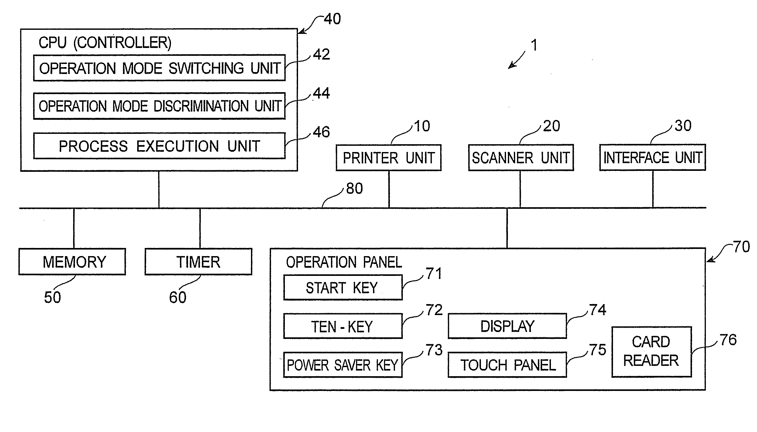
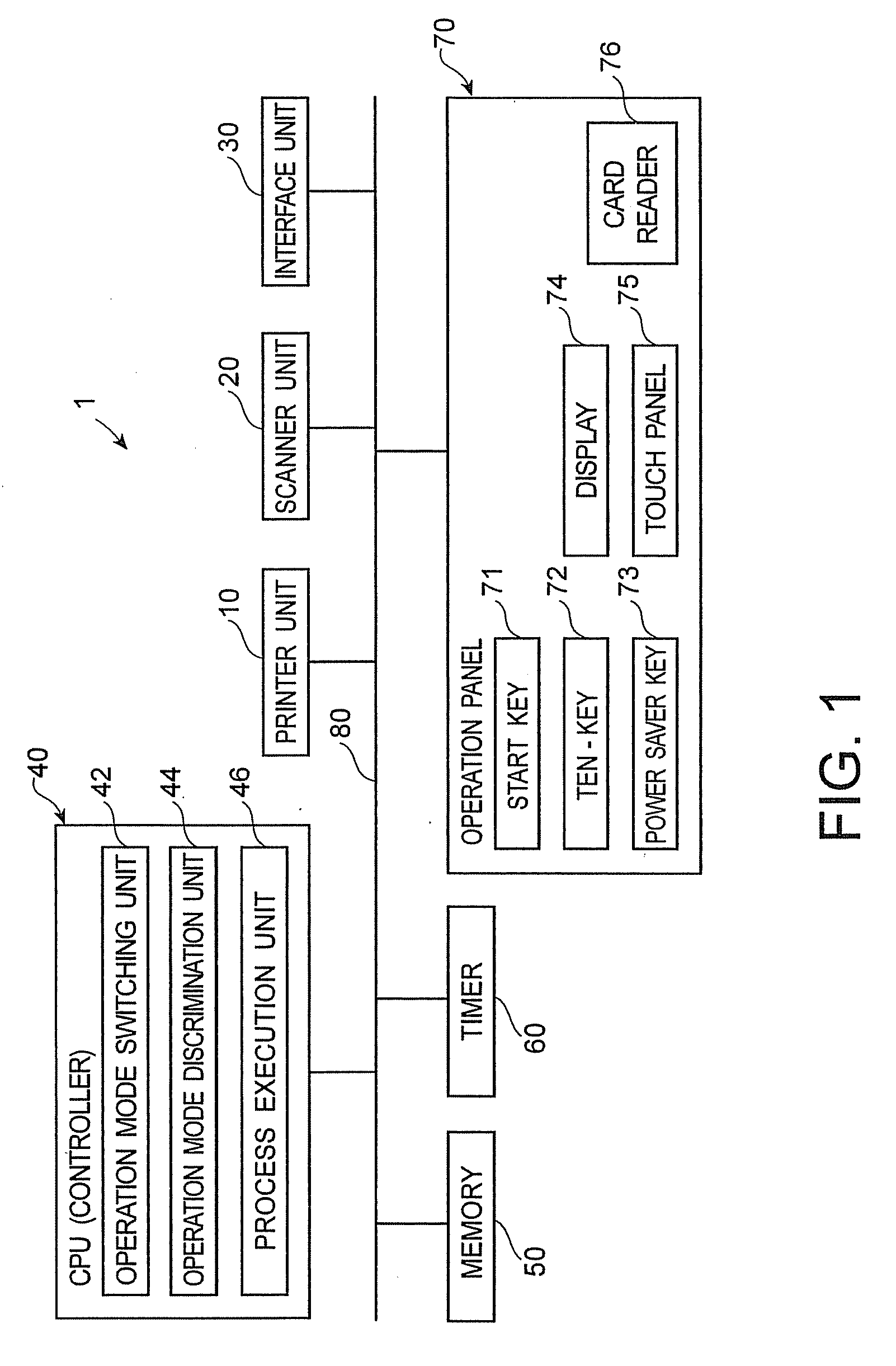
[0021]The embodiment of the present invention will be explained below with reference to the accompanying drawings. FIG. 1 is a function block diagram for explaining an image processing apparatus (MFP: multi function peripheral) 1 of this embodiment. The image processing apparatus 1 of this embodiment can switch the operation mode between the “ordinary power supplying mode” and the “power saving mode” for suppressing power consumption more than the ordinary power supplying mode.

[0022]As shown in FIG. 1, the image processing apparatus 1 of this embodiment is composed of a printer unit 10, a scanner unit 20, an interface unit 30, a controller 40, a memory 50, a timer 60, and an operation panel 70 and these units are mutually connected via a bus 80.

[0023]The controller 40 is composed of an operation mode switching unit 42, an operation mode discrimination unit 44, and a process execution unit 46.

[0024]The operation panel 70 is installed on the top of the main unit of the processing appa...


PUM


Abstract

To provide an image processing apparatus for switching an operation mode between an ordinary power supplying mode and a power saving mode for suppressing power consumption more than the ordinary power supplying mode. The image processing apparatus includes an operation panel operated by a user to execute an operation of the image processing apparatus, a display unit to display a state of the image processing apparatus and various instructions to the user on the operation panel, a discrimination information obtaining unit to obtain a user discrimination information from a non-contact medium in which the user discrimination information is stored to permit use of the image processing apparatus, an information discrimination unit to discriminate approval or disapproval of use of the image processing apparatus from the user discrimination information obtained by the discrimination information obtaining unit, an operation mode discrimination unit to discriminate whether the operation panel is operated and the operation mode of the image processing apparatus is switched from the power saving mode to the ordinary power supplying mode or not, and a control unit to control the display unit to display that the use of the image processing apparatus is permitted when the operation mode discrimination unit discriminates that the operation mode of the image processing apparatus is switched to the ordinary power supplying mode after the image processing apparatus obtains the user discrimination information from the discrimination information obtaining unit on the power saving mode and when the information discrimination unit discriminates that the image processing apparatus is permitted to use.

Description

CROSS-REFERENCE TO RELATED APPLICATION[0001]This application is based upon and claims the benefit of priority from the prior Japanese Patent Application No. 2006-7515 filed on Jan. 16, 2006, the entire contents of which are incorporated herein by reference.BACKGROUND[0002]1. Field of the Invention[0003]The present invention relates to an image processing apparatus for performing management concerning a predetermined process executed in the image processing apparatus capable of switching an operation mode and an operation mode switching control method for the image processing apparatus.[0004]2. Description of the Related Art[0005]Conventionally, in an image processing apparatus for forming an image on a sheet and reading an image of a document, an art for switching an operation mode between an ordinary power supplying mode and a power saving mode (the so-called sleep mode) for suppressing power consumption more than the ordinary power supplying mode is known. Further, in recent years...

Claims


Application Information

Patent Timeline
IPC IPC(8): G06F3/12G06K15/00
CPCG03G15/5016G03G15/5004
Inventor WATANABE, HIROSHIIWASAKI, TAKAOMATSUMOTO, BENIKO
Owner KK TOSHIBA
Learn More