Deformable mirror device, deformable mirror plate

a deformation mirror and mirror plate technology, applied in the direction of mirrors, instruments, data recording, etc., can solve the problems of complex overall arrangement, difficult to arrange a plurality of piezoelectric actuators in such an area, and complex piezoelectric actuators

Inactive Publication Date: 2007-07-19
SONY CORP
View PDF11 Cites 30 Cited by
  • Summary
  • Abstract
  • Description
  • Claims
  • Application Information

AI Technical Summary

Benefits of technology

[0010] In view of the above-identified circumstances, it is therefore the object of the present invention to provide a novel deformable mirror device and a deformable mirror plate that can dissolve the problem of the conventional art.
[0016] According to the present invention, it is possible to obtain a profile that is deformed stepwise in a desired manner for the flexible member according to the level of the drive force applied to it. Thus, it is possible to produce two or more than two types of deformed profile for the mirror surface. Then, if an optical disc has three or more than three signal recording layers, it is possible to effectively correct spherical aberration for any of the signal recording layers other than the one selected as reference signal recording layer when designing the corresponding optical system.
[0017] Still additionally, according to the present invention, it is possible to realize a deformable mirror device that can compensate spherical aberration for any variations of flexible member such as one adapted to reflect a laser beam by 180° and one adapted to reflect a laser beam by 90° by forming parts so as to be in a state differentiated from the remaining parts in terms of mode of deformation due to the profiles of circles or ellipses thereof having a common center. Then, as a result of forming parts showing profiles of circles or ellipses having a common center, it is possible to prevent areas intensively subjected to stress from arising when drive force is applied. Thus, it is possible to effectively prevent the flexible member from being broken and / or fractured by fatigue if it is deformed repeatedly.

Problems solved by technology

Of the above-cited arrangements, that of providing piezoelectric actuators is complex because of the necessity of using a plurality of piezoelectric actuators in order to make the mirror surface show a predetermined profile.
Then, the control circuit for controlling the operation of driving the plurality of piezoelectric actuators inevitably shows large dimensions and makes the overall arrangement a very complex one.
Then, it is highly difficult to arrange a plurality of piezoelectric actuators in an area of such a dimension.
With an optical system using such a deformable mirror, it is not possible to effectively correct the spherical aberration of an optical disc having three or more than three signal recording layers.

Method used


Image

  • Deformable mirror device, deformable mirror plate
  • Deformable mirror device, deformable mirror plate
  • Deformable mirror device, deformable mirror plate

Examples


first embodiment

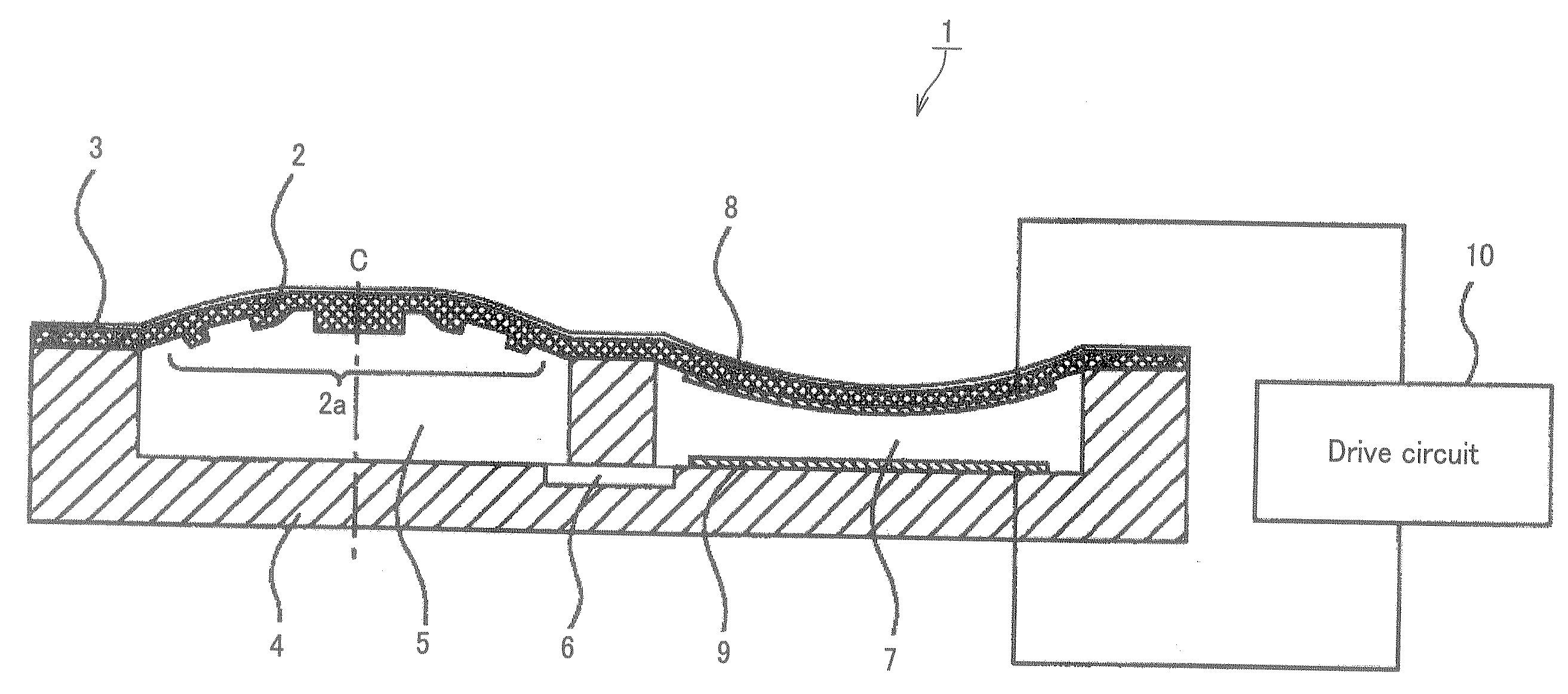
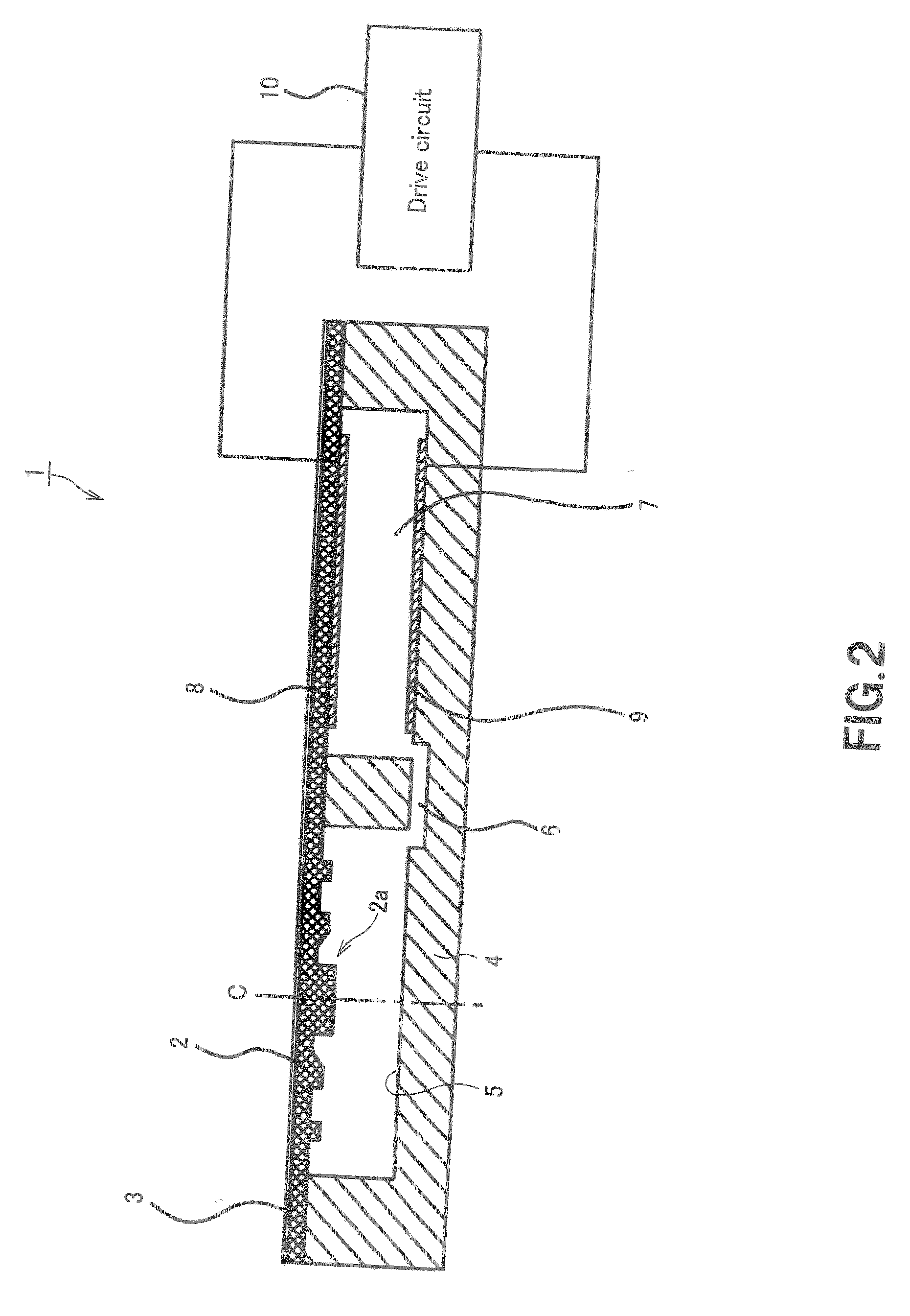
[0068] Firstly, the first embodiment of a deformable mirror device 1 according to the present invention will be described below by referring to FIG. 2. The deformable mirror device 1 deforms a mirror surface by using a flexible member that takes a differentiated partial state in a deformation mode as the part where the cross section profile is differentiated is formed and a strength distribution pattern is given.

[0069] As shown in FIG. 2, the deformable mirror device 1 according to the invention includes at least a flexible member 2, a reflection film 3, a substrate 4, an upper electrode 8 and a lower electrode 9. The substrate 4 of the mirror device 1 is provided with two circular grooves for producing a first space 5 and a second space 7, the two grooves being arranged side by side. The first space 5 and the second space 7 defined by the two grooves are linked to each other by way of a flow channel 6.

[0070] The flexible member 2 is bonded to the substrate 4 so as to cover the fi...

second embodiment

[0101] Now, the second embodiment of the present invention will be described below by referring to FIG. 6. The deformable mirror device 20 of the second embodiment differs from the first embodiment in that while the first embodiment is adapted to produce drive force for deforming the mirror surface by the attractive force between the upper electrode 8 and the lower electrode 9, the second embodiment is adapted to produce drive force for deforming the mirror surface by way of deformation of a piezoelectric element 21.

[0102] In FIG. 6, the components same as those of the first embodiment are denoted respectively by the same reference symbols and will not be described any further.

[0103] In the deformable mirror device 20, the flexible member 2 is bonded to the substrate 4 so as to cover only the first space 5 as shown in FIG. 6. At the side of the second space 7, an elastic conductive plate 22 is bonded to the substrate 4 so as to cover only the second space 7. The elastic conductive...

third embodiment

[0113] Now, the third embodiment of the present invention will be described below by referring to FIG. 7. The deformable mirror device 30 of the third embodiment is adapted to deform the mirror surface by directly pushing or pulling the surface of the flexible member 2 where the strength distribution pattern 2a is formed by means of a voice coil motor.

[0114] As shown in FIG. 7, the mirror device 30 has a single circular space 37 in a substrate 4. The flexible member 2 is bonded to the substrate 4 in such a way that the central axis C of the circular space 37 is aligned with the center of the strength distribution pattern 2a that shows concentrically arranged circles. A voice coil motor 31 is fitted to the substrate 4 in the space 37.

[0115] The voice coil motor 31 is rigidly secured in position on the substrate 4 with the central axis of the cylindrical yoke 32 thereof aligned with the central axis C of the space 37. The cylindrical yoke 32 is provided with a flange section and a r...


PUM


Abstract

A deformable mirror device compensates the spherical aberration caused by the difference of thickness of the cover layers covering recording layers of an optical disc. Circular projections are concentrically arranged on a flexible member (2) where a mirror surface (3) is formed to produce a strength distribution pattern (2a). Attractive force is generated as electrostatic force between an upper electrode (8) and a lower electrode (9) according to the voltage applied from a drive circuit (10) so as to contract the second space (7) and accordingly expand the first space (5) in order to deform the mirror surface. At this time, the profile of the mirror surface is deformed to show a desired profile that can compensate the spherical aberration by the pattern formed on the flexible member (2) as strength distribution pattern (2a). With this arrangement, only a single drive actuator (10) is needed to deform the mirror surface to simplify the configuration and the control operation. The mirror surface can be deformed stepwise to show predetermined deformed profiles depending on the pattern formed as strength distribution pattern (2a). Then, it is possible to compensate the spherical aberration for each of the three or more than three recording layers of the optical disc.

Description

TECHNICAL FIELD [0001] This invention relates to a deformable mirror device having a deformable mirror surface and also to a deformable mirror plate. [0002] This application is based upon and claims the benefit of priority from the prior Japanese Patent Applications No. 2004-223018 filed on Jul. 30, 2004, No. 2004-319123 filed on Nov. 2, 2004 and No. 2005-129576 filed on Apr. 27, 2005, the entire contents of which being incorporated herein by reference. BACKGROUND ART [0003] In optical disc apparatus adapted to record information signals on or reproduce information signals from an optical disc that operates as information recording medium, a laser beam emitted from a laser beam source is converged by an objective lens and irradiated onto the signal recording layer of the optical disc to record or reproduce signals. When a laser beam is irradiated by way of an objective lens, spherical aberration appears depending on the thickness of the cover layer covering the recording layer of th...

Claims


Application Information

Patent Timeline
Patent Type & Authority Applications(United States)
IPC IPC(8): G02B5/08
CPCG02B26/0825G02B27/0068G11B7/0948G11B2007/0013G11B7/13925G11B7/13927G11B7/1362G02B26/08
Inventor AOKI, SUNAOMIURA, TAKAHIROYAMADA, MASAHIRO
Owner SONY CORP
Why Eureka
Try Eureka