Digital pulse width modulation controlling system and method

a control system and digital pulse technology, applied in the direction of power conversion systems, dc-dc conversion, electrical equipment, etc., can solve the problems of increasing the design complexity and cost expenditure of the controlling system, the whole control system b>10/b> is vulnerable to noise, and the addition of additional elements generally brings to a higher cost, so as to achieve efficient and effective control of the load of the electronic devi

Inactive Publication Date: 2007-07-19
HOLTEK SEMICON
View PDF7 Cites 4 Cited by
  • Summary
  • Abstract
  • Description
  • Claims
  • Application Information

AI Technical Summary

Benefits of technology

[0011] With execution of the inventive DPWM controlling system and method, the control of the load of the electronic device can be efficiently and effectively achieved. Thus, the demerits existing in the prior art may be eliminated.

Problems solved by technology

However, the frequency of the ramp signal Vramp is not stable, causing the whole control system 10 to be vulnerable to noises.
However, the additional elements generally bring to a higher cost.
As such, an increased data amount has to be processed in the controlling system, increasing design complexity and cost expenditure of the controlling system.

Method used


Image

  • Digital pulse width modulation controlling system and method
  • Digital pulse width modulation controlling system and method
  • Digital pulse width modulation controlling system and method

Examples


Embodiment Construction

[0022] The present invention discloses a digital pulse width modulation (DPWM) controlling system and method, which will be described through the preferred embodiments with reference to the appended drawings.

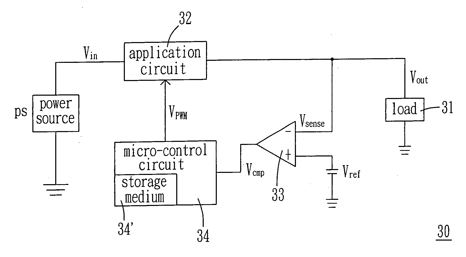
[0023] Referring to FIG. 3, a schematic diagram of the DPWM controlling system is shown therein. The DPWM controlling system comprises a load 31, an application circuit 32, a comparator 33 and a micro-control unit 34. In operation, the application circuit 32 receives a power signal Vin from a direct current (DC) power source PS and outputs a digital signal Vout to control the load 31. The comparator 33 is used to compare the output signal Vout and a reference signal Vref to generate a comparison signal Vcmp. The micro-control unit 34 is used to receive the comparison signal Vcmp to generate a DPWM signal VPWM to control the application circuit 32 and thus the load 31 thereof. Alternatively, the power source PS may be an alternating current (AC) power source and the application ...


PUM


Abstract

A digital pulse width modulation (DPWM) controlling system for controlling a load of an application circuit with a DPWM unit is provided, which comprises a comparator and a micro-control unit, the comparator receiving a sense signal detected from the load and a reference signal and comparing the sense signal and the reference signal to output an analog comparison signal, and the micro-control unit generating a trigger signal having a minimum pulse width and receiving the analog comparison signal to output a DPWM signal, wherein the micro-control unit adjusts the minimum pulse width of the trigger signal to obtain a pulse width of the DPWM signal in response to the analog comparison signal whenever the sense signal is within a stable duration so as to output the DPWM signal to the application circuit to control the load.

Description

FIELD OF THE INVENTION [0001] The present invention relates to a digital pulse width modulation (DPWM) controlling system and method. More particularly, the present invention relates to a DPWM controlling system and method without the need of an analog-to-digital (ADC) converter. BACKGROUND OF THE INVENTION [0002] The pulse width modulation (PWM) controlling system is a system usually used for controlling an electronic device. In essence, an output signal on a load of the electronic device is first detected as a sense signal. Then, the sense signal is compared with a reference signal to obtain a comparison result. Then, a predetermined pulse width is formed as a signal based on the comparison result to serve as a PWM signal by which the electronic device is controlled. Correspondingly, the load is controlled via the electronic device. Namely, the PWM control signal is adjusted by means of the negative feedback technology and then the adjusted PWM control signal is issued to control ...

Claims


Application Information

Patent Timeline
Patent Type & Authority Applications(United States)
IPC IPC(8): H02M1/12
CPCH02M3/157
Inventor LIN, YI-CHANHOU, YUEH-MEILAI, CHIEN-FENGLIU, YI-CHEN
Owner HOLTEK SEMICON
Why Eureka
Try Eureka