X-ray ct apparatus and medical data communication link system
a technology of x-ray ct and x-ray ct, which is applied in the direction of material analysis using wave/particle radiation, instruments, applications, etc., can solve the problems of increasing the width of the system, increasing the space required for installation of the x-ray ct apparatus, and not being able to meet the above requirements, etc., to achieve high data rate transmission
- Summary
- Abstract
- Description
- Claims
- Application Information
AI Technical Summary
Benefits of technology
Problems solved by technology
Method used
Image
Examples
first embodiment
[First Embodiment of the Medical Data Communication Link System]
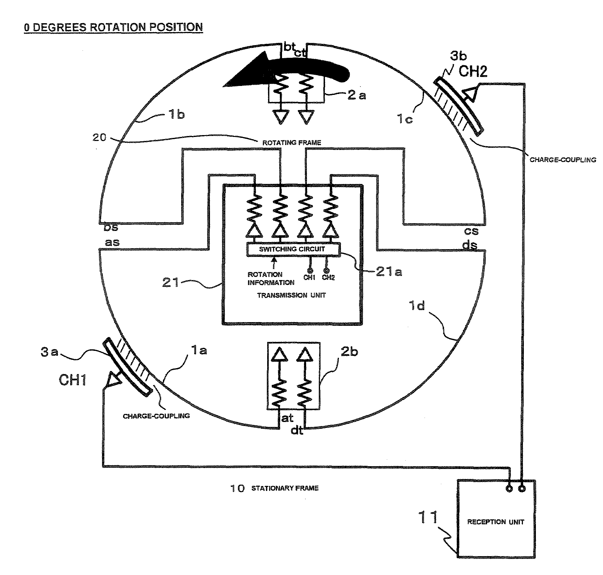
[0035]FIG. 4 typically shows the constitution of the rotating frame 20 and the stationary frame 10 at the initial stage of rotation (with an angle of rotation of 0 degrees for example). For the rotating frame 20, a transmission medium 1a, transmission medium 1b, transmission medium 1c and transmission medium 1d (hereinafter, “Transmission medium 1” indicates any of the medium individually) are provided in a line in intervals around the circumference of the rotating frame 20. Each transmission medium 1 forms a strip line extending around the circumference. On the stationary frame 10, a receiving medium 3a and a receiving medium 3b (hereinafter “Receiving medium 3” indicates any of the medium individually) are mounted.
[0036]The interval between the transmission medium 1 (between ends as—bs, ends bt—ct, ends cs—ds, and ends dt—at in FIG. 4) is shorter than each length of the receiving medium 3a and the receiving medium 3b ...
second embodiment
[Second Embodiment of the Communication System]
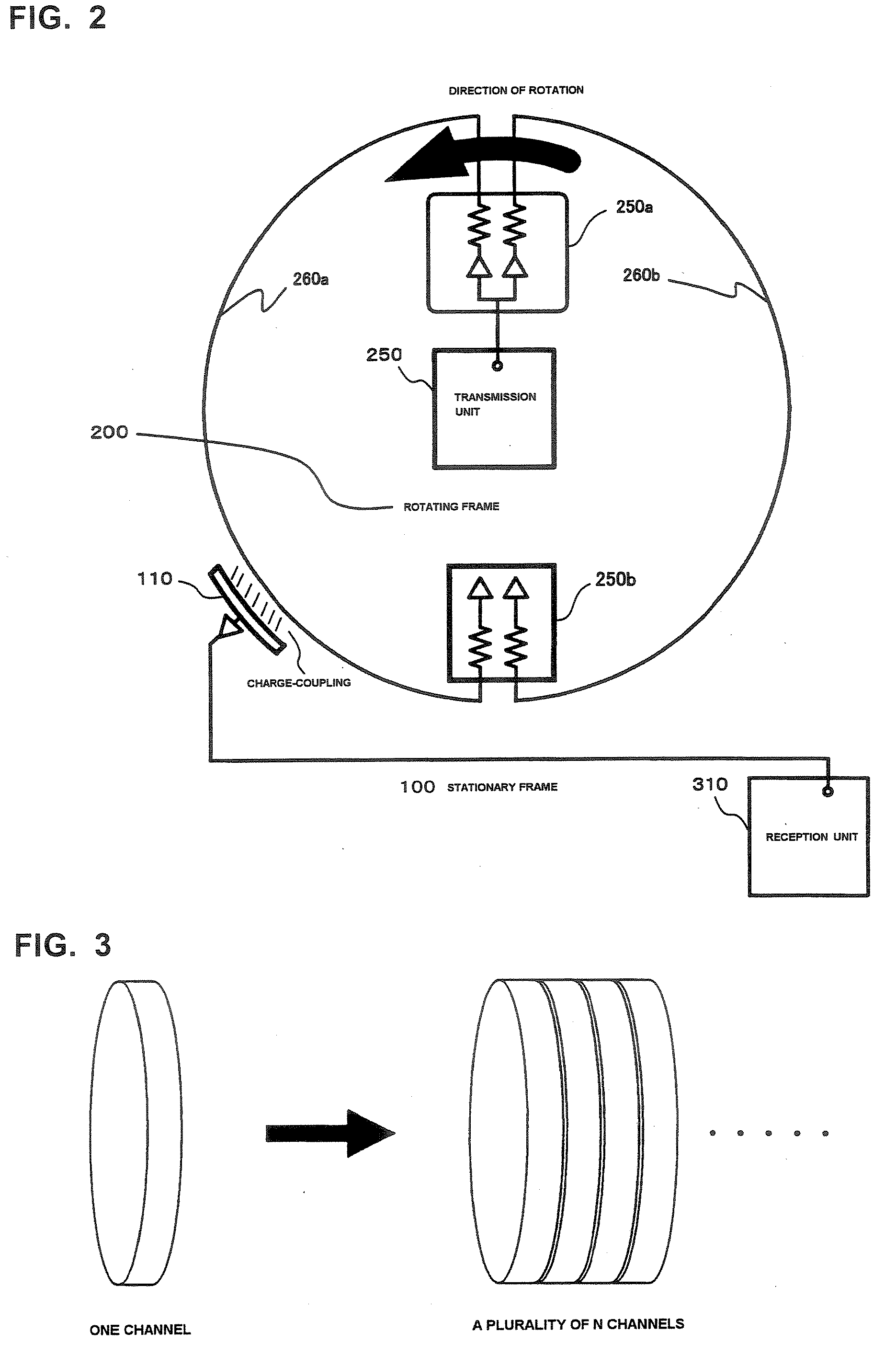
[0056]FIGS. 10 and 11 show an example expanding up to three channels. The conditions for this expansion include a number of receiving medium 3 more than N components and the number of transmission medium 1 more than 2N components relative to the channel of several N components.
[0057]FIG. 10 shows three-channel communication, wherein the number was increased proportionate to the number in the composition / action of the first embodiment for two-channel communication. Accordingly, the dimensions, arrangement, and action in response to the rotation angle become smaller according to the number of channels; however, the technological concept is the same, for which a brief explanation is given below.
[0058]FIG. 10 shows the typical constitution of a rotating frame 20A with a rotation angle of 0 degrees and the stationary frame 10A. At the rotating frame 20A, the 6 transmission medium 1e-1k (excluding 1i) (hereinafter, “Transmission medium 1” ind...
third embodiment
[Third Embodiment of the Communication System]
[0064]FIG. 12 provides an example of an embodiment enabling three-channel communication shown in FIG. 10, wherein the receiving medium 3e is excluded to modify into two-channel communication.
[0065]The third embodiment shows that N channel communication is possible if the number of transmission medium 1 counts for more than M components exceeding 2N components. FIG. 12 is an example wherein the number of transmission medium 1 is counted as 6 components (M=6) with two channels (N=2). M=5, 7, etc. is also possible with N=2.
[0066]In FIG. 12, the switching circuit 22a may be switched in the same way as in FIG. 11. Only the signal from channel CH3 is not transferred. When a signal generated in the signal generation of channel CH3 by the transmission unit 22 will be unused, the signal from CH3 shown in FIG. 11 will be eliminated, but this is acceptable; however, the signal from CH3 shown in FIG. 11 may equal the channel signal from the adjacent...
PUM
 Abstract
Description
Claims
Application Information
 - R&D
- Intellectual Property
- Life Sciences
- Materials
- Tech Scout
- Unparalleled Data Quality
- Higher Quality Content
- 60% Fewer Hallucinations
Browse by: Latest US Patents, China's latest patents, Technical Efficacy Thesaurus, Application Domain, Technology Topic, Popular Technical Reports.
© 2025 PatSnap. All rights reserved.Legal|Privacy policy|Modern Slavery Act Transparency Statement|Sitemap|About US| Contact US: help@patsnap.com


