
Beamlet blanker arrangement

Active Publication Date: 2012-04-19
ASML NETHERLANDS BV
View PDF3 Cites 25 Cited by
  • Summary
  • Abstract
  • Description
  • Claims
  • Application Information

AI Technical Summary

Benefits of technology

[0015]It is an object of the invention to provide a lithography system enabling high data rate transmission of control signals to individual deflectors.
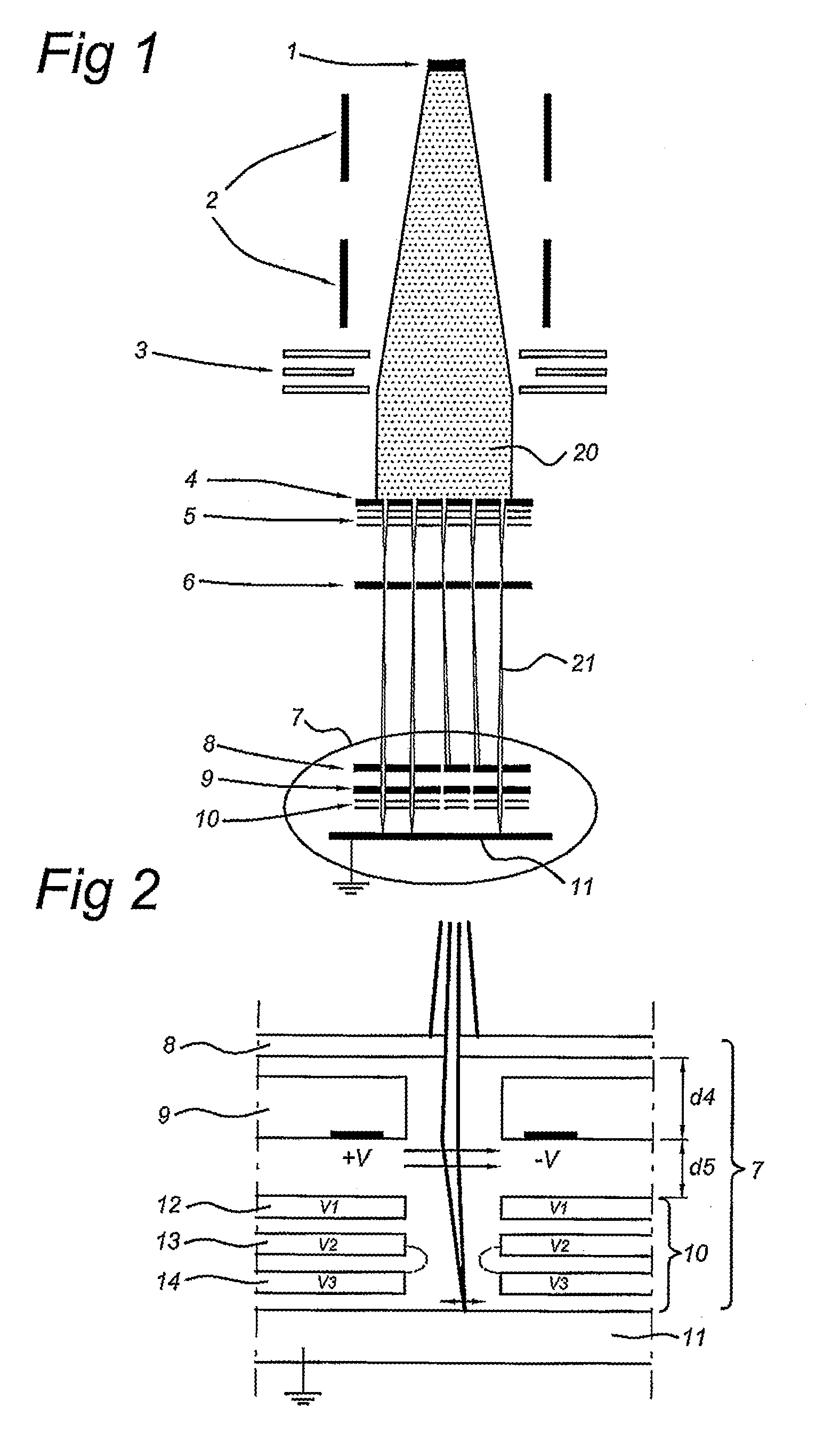
[0055]There are several advantages to the use of electrodes with concave shape. Most relevant is that the concave shapes is conformal to the shape of the aperture. This aperture then most suitably has circular cross-section in the plane of the blanker. Preferably, the aperture is cylindrical in total. Such a shape of the aperture prevents introduction of astigmatistic aberrations, which might result from block-shaped apertures. It moreover reduces interactions between neighbouring deflectors. Both effects support to improve the accuracy of the deflector. They also help to enable a denser packing of deflectors.

Problems solved by technology

This greatly increased throughput poses an engineering challenge to adequately control the deflection of the beamlets.
This is made more critical because errors during blanking of the beamlets cannot be corrected during a lithography process, so that specifications for a beamlet blanker need to be ultimately strict.

Method used


Image

  • Beamlet blanker arrangement
  • Beamlet blanker arrangement
  • Beamlet blanker arrangement

Examples


Embodiment Construction

[0079]The following is a description of various embodiments of the invention, given by way of example only and with reference to the drawings.

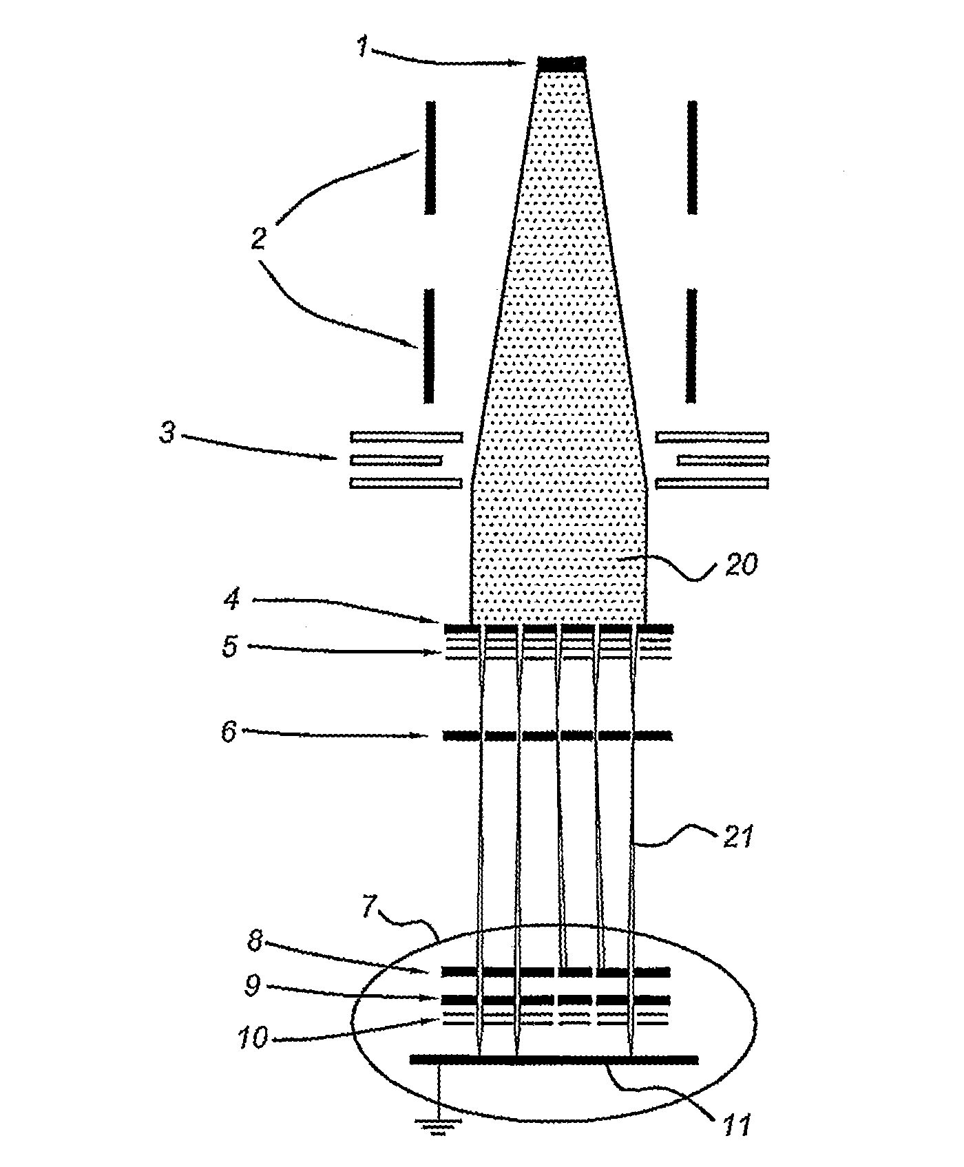
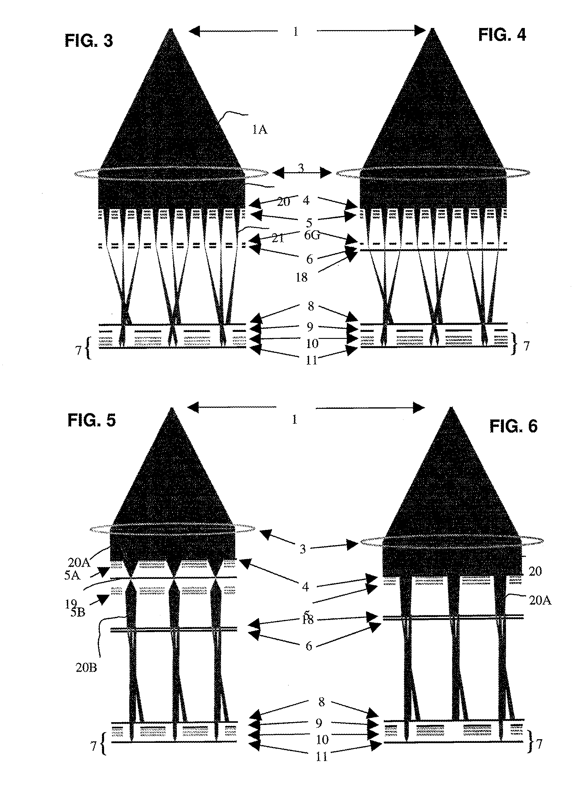
[0080]FIG. 1 shows a simplified schematic drawing of an embodiment of a charged particle multi-beamlet lithography system based upon an electron beam optical system without a common cross-over of all the electron beamlets. Such lithography systems are described for example in U.S. Pat. Nos. 6,897,458 and 6,958,804 and 7,084,414 and 7,129,502 which are all hereby incorporated by reference in their entirety, assigned to the owner of the present invention. In the embodiment shown in FIG. 1, the lithography system comprises an electron source 1 for producing a homogeneous, expanding electron beam 20. Beam energy is preferably maintained relatively low in the range of about 1 to 10 keV. To achieve this, the acceleration voltage is preferably low, the electron source preferably kept at between about −1 to −10 kV with respect to the target at ground ...


PUM


Abstract

The invention relates to a charged particle multi-beamlet lithography system for exposing a target using a plurality of beamlets. The system has a beam generator, a beamlet blanker, and a beamlet projector. The beam generator is configured to generate a plurality of charged particle beamlets. The beamlet blanker is configured to pattern the beamlets. The beamlet projector is configured to project the patterned beamlets onto the target surface. The system further has a deflection device. The deflection device has a plurality of memory cells. Each memory cell is provided with a storage element and is connected to a switching electrode of a deflector.

Description

BACKGROUND OF THE INVENTION[0001]1. Field of the Invention[0002]The present invention relates to a projection system for a charged particle multi-beamlet system, such as for a charged particle multi-beamlet lithography system or an inspection system, and an end module for such a projection system.[0003]The present invention more specifically relates to a deflection device, in particular a beamlet blanker for use in a charged particle multi-beamlet lithography system, the blanker comprising a substrate provided with apertures and deflectors with a first electrode and a second electrode arranged around an aperture, the deflectors receiving electrical signals for deflecting beamlets of charged particles passing through the apertures.[0004]The present invention further relates to a charged particle multi-beamlet lithography system, to a deflecting method and a method of transferring a pattern to a target surface.[0005]2. Description of the Related Art[0006]Currently, most commercial lit...

Claims


Application Information

Patent Timeline
IPC IPC(8): H01J3/26G01J1/44
CPCB82Y10/00B82Y40/00H01J37/045H01J37/3177H01J2237/31762H01J2237/0492H01J2237/1504H01J2237/2485H01J2237/0437
Inventor WIELAND, MARCO JAN JACOVAN VEEN, ALEXANDER HENDRIK VINCENT
Owner ASML NETHERLANDS BV
Learn More