Auto frequency calibrator, method thereof and frequency synthesizer using it

Inactive Publication Date: 2011-02-10
SAMSUNG ELECTRO MECHANICS CO LTD
11 Cites 13 Cited by

AI-Extracted Technical Summary

Problems solved by technology

In addition, since the selected capacitor bank does not reflect the change according to temperature, the frequency synthesizer may be unlocked and since a gain of the voltage controlled oscillator is not constant, the characteristics of the frequency synthesizer are deteriorated.
For this reason, it becomes the closed loop and then does not apply the ...

Benefits of technology

0042]In the embodiment of the present invention, the auto frequency calibrator, which finds out the capacitor bank corresponding to the desired output frequency, can reflect the integer divider value as well as the fractional divider value and the gain of the voltage controlled oscillator can select a constant interval to prevent the loop of the frequency synthe...

Abstract

The present invention relates to and auto frequency calibrator, a method thereof, and a frequency synthesizer using it. The auto frequency calibrator includes a capacitor bank selector that is operated as an open loop and compares a frequency signal having integer-divided reference frequency with the reference frequency signal to select a capacitor bank corresponding to an output frequency; and a capacitor bank controller that is operated as a closed loop when the capacitor bank is selected and compares the output voltage corresponding to the output frequency with a preset voltage range to control the capacitor bank selected in the capacitor bank selector.

Application Domain

Pulse automatic control

Technology Topic

Voltage rangeElectrical and Electronics engineering +4

Image

  • Auto frequency calibrator, method thereof and frequency synthesizer using it
  • Auto frequency calibrator, method thereof and frequency synthesizer using it
  • Auto frequency calibrator, method thereof and frequency synthesizer using it

Examples

  • Experimental program(1)

Example

[0050]Although the present invention can be modified variously and have several embodiments, the exemplary embodiments are illustrated in the accompanying drawings and will be described in detail in the detailed description. However, the present invention is not limited to the specific embodiments and should be construed as including all the changes, equivalents, and substitutions included in the spirit and scope of the present invention.
[0051]Hereinafter, an auto frequency calibrator, a method of automatically calibrating a frequency, and a frequency synthesizer using it according to the exemplary embodiment of the present invention will be described with reference to the accompanying drawings. Like reference numerals refer to like components and the duplicated description thereof will be omitted.
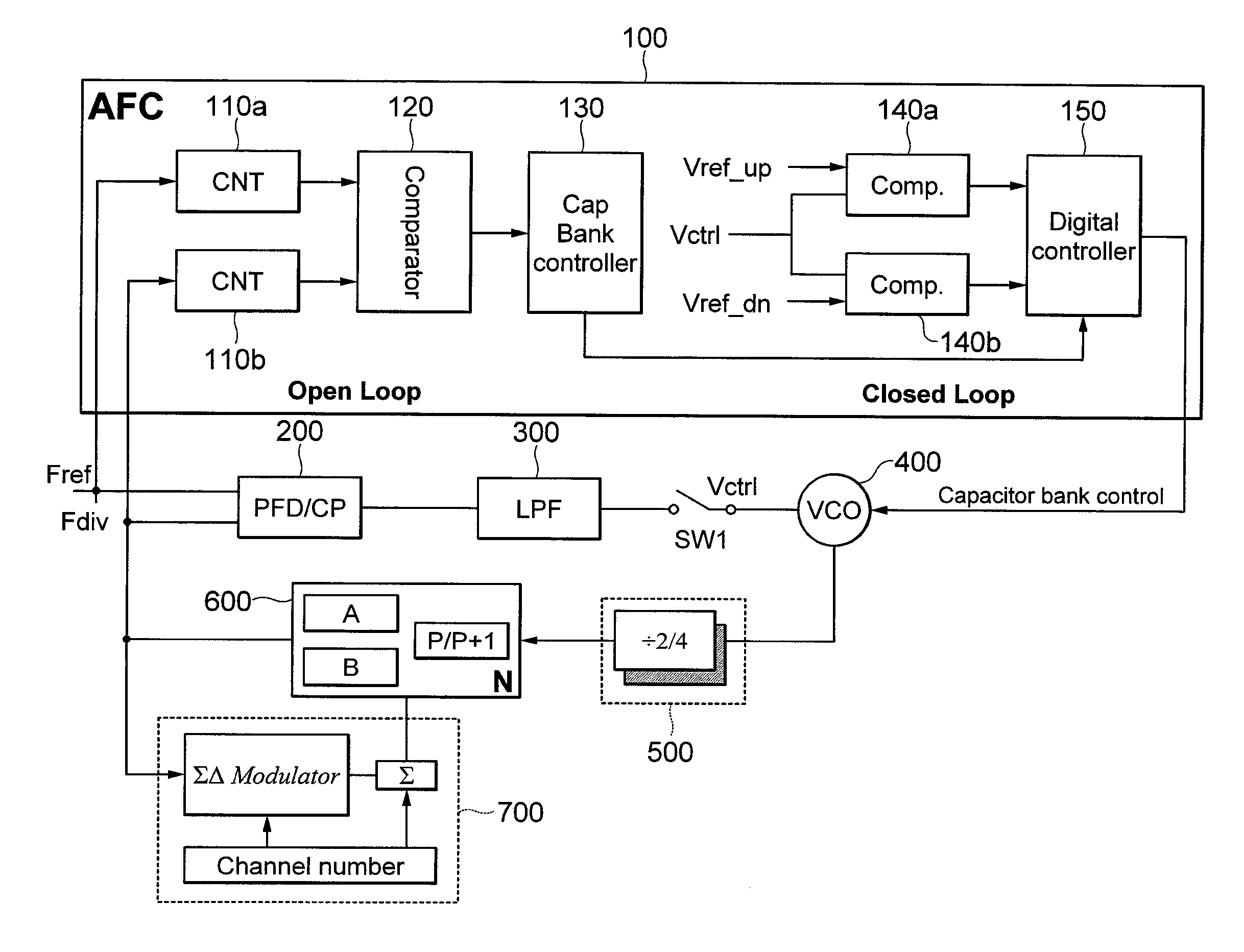
[0052]FIG. 4 is a diagram showing a configuration of an auto frequency calibrator according to an exemplary embodiment of the present invention.
[0053]As shown in FIG. 4, an auto frequency calibrator 100 includes a capacitor bank selector and a capacitor bank controller. The capacitor bank selector includes a first counter 110a, a second counter 110b, a comparator 120, and a capacitor bank selection controller 130. The capacitor bank controller includes a first voltage comparator 140a, a second voltage comparator 140b, and a capacitor bank control controller 150.
[0054]The capacitor bank selector is operated as an open loop and compares a frequency signal having an integer-divided frequency signal with the reference frequency signal to select a capacitor bank corresponding to an output frequency.
[0055]The capacitor bank controller is operated as a closed loop when the capacitor bank is selected and compares the output voltage corresponding to the output frequency with a predetermined voltage range to control the capacitor bank selected in the capacitor bank selector.
[0056]In other words, the capacitor bank selector considers only the integer divider value to select the capacitor bank and the capacitor bank controller reflects a fractional divider value to control the capacitor bank.
[0057]While the frequency synthesizer is operated as the open loop, an output voltage from an voltage controlled oscillator is fixed to a value corresponding to VDD/2 and an output frequency signal corresponding to VDD/2 is provided to the capacitor bank selector of the auto frequency calibrator.
[0058]First, the capacitor bank selector of the auto frequency calibrator is configured to include a first counter 110a, a second counter 110b, a comparator 120, and a capacitor bank selection controller 130, wherein the first counter 110b counts the frequency signal having an integer-divided frequency signal, which is generated from the oscillator and the second counter 110a counts the reference frequency signal.
[0059]The comparator 120 compares signals counted in the first counter 110b and the second counter 110a and the capacitor bank selection controller 130 generates a control signal that controls the selection of the capacitor bank from the compared signals.
[0060]In other words, the bank selection controller 130 compares the frequency signal having an integer-divided reference signal with the reference frequency signal in the first counter 110b or the second counter 110a to generate the control signal that selects the capacitor bank up or down.
[0061]Next, the capacitor bank controller of the auto frequency calibrator 100 includes the first voltage comparator 140a, the second voltage comparator 140b, and the capacitor bank control controller 150.
[0062]The first voltage comparator 140a compares the output voltage corresponding to the output frequency of the voltage controlled oscillator with a predetermined maximum voltage and the second voltage comparator 140b compares the output voltage corresponding to the output frequency with a predetermined minimum voltage.
[0063]The capacitor bank control controller 150 compares the maximum voltage or the minimum voltage with the output voltage in the first voltage comparator 140a or the second voltage comparator 140b to generate a control signal that controls the capacitor bank up or down.
[0064]Therefore, the auto frequency calibrator according to the related art, which is operated as the open loop and selects the capacitor bank in consideration of the fractional divider value, does not reflect any fractional divider values, while the auto frequency calibrator according to the present invention selects the capacitor bank in consideration of the integer divider value when it is operated as the open loop and can reflect any fractional divider value when it is operated as the closed loop to control the capacitor bank, such that there is no need to separately correct a charge pump or a loop pump when the auto frequency calibrator is operated as the closed loop.
[0065]The frequency synthesizer according to another embodiment of the present invention includes the auto frequency calibrator 100 and a loop switching element SW1.
[0066]The frequency synthesizer includes the auto frequency calibrator 100, a phase frequency divider (PFD) 200, a charge pump (CP) 200, a low pass filter (LPF) 300, an voltage controlled oscillator (VCO) 400, first and second dividers 500 and 600, and a signal-delta divider 700.
[0067]The auto frequency calibrator 100 has the above-mentioned features and the phase frequency divider (PFD) 200, the charge pump (CP) 200, the low pass filter (LPF) 300, the voltage controlled oscillator (VCO) 400, the first and second dividers 500 and 600, and the signal-delta divider 700 all of which are included in the frequency synthesizer according to an exemplary embodiment of the present invention have general characteristics.
[0068]The loop of the frequency synthesizer according to the exemplary embodiment of the present invention is operated as the open loop and the closed loop by the on/off of the loop switching element SW1 and transmits the control signal that closes the loop switching element SW1 to be operated as the closed loop when the capacitor bank is selected in the capacitor bank selector of the auto frequency calibrator 100.
[0069]In addition, the loop switching element SW1 detects an output voltage Vctrl corresponding to the output frequency of the voltage controlled oscillator 400 when it is operated as the closed loop and transmits the detected output voltage to the capacitor bank controller of the auto frequency calibrator 100.
[0070]The voltage controlled oscillator 400 includes a plurality of capacitors that are connected to each other in parallel and a switching element that can switch each capacitor and outputs an oscillation frequency corresponding to the capacitor bank controlled in the capacitor bank controller.
[0071]A method of automatically calibrating a frequency is a method that selects a capacitor bank, which is operated as an open loop, according to an integer-divided frequency signal and then controls the capacitor bank, which is operated as a closed loop, by measuring an output voltage.
[0072]FIG. 5 is a diagram showing a flowchart of a method of automatically calibrating a frequency according to an exemplary embodiment of the present invention.
[0073]As shown in FIG. 5, the method of automatically calibrating a frequency according to an exemplary embodiment of the present invention opens the loop switching element SW1 so that the loop of the frequency synthesizer is operated as the open loop and initializes the output voltage Vctrl to VDD/2 (S501) and then compares a reference frequency signal Fref with an integer-divided frequency signal Fdiv to select a capacitor bank corresponding to the output frequency (S502).
[0074]The method of automatically calibrating a frequency compares the reference frequency signal Fref with the integer-divided frequency signal Fdiv and controls the capacitor bank corresponding to the integer-divided frequency signal Fdiv up or down so that the integer-divided frequency signal Fdiv conforms to the reference frequency signal Fref (S502 to S504).
[0075]When the capacitor bank corresponding to the integer-divided frequency signal Fdiv is selected so that the integer-divided frequency signal Fdiv conforms to the reference frequency signal Fref, the loop switching element SW1 is closed to form the closed loop (S504).
[0076]When the closed loops is formed, the output voltage Vctrl corresponding to the output frequency of the voltage controlled oscillator compares with the predetermined voltage ranges Vdown and Vup to control the capacitor bank selected in the capacitor bank selector.
[0077]The controlling the capacitor bank (S506 to S510) includes forming the closed loop by connecting the loop switching element SW1 (S506), maintaining the closed loop and measuring the output voltage Vctrl, comparing the measured output voltage Vctrl with the predetermined maximum Vup or minimum voltage Vdown (S507), and controlling the capacitor bank up when the measured output voltage Vctrl is larger than the maximum voltage Vup (S510), and controlling the capacitor bank down when the measured output voltage Vctrl is smaller than the minimum voltage Vdown (S508).
[0078]In other words, after the capacitor bank is selected in consideration of the integer-divided frequency signal, the output voltage from the voltage controlled oscillator is detected to consider the linearity of the fractional-divided frequency and gain while the frequency synthesizer is operated as the closed loop and the capacitor bank is controlled so that the output voltage is included in the predetermined voltage range.
[0079]FIG. 6 is a diagram showing simulation results for describing a method of selecting and controlling the capacitor bank of the auto frequency calibrator according to the exemplary embodiment of the present invention.
[0080]FIG. 6 shows a process of operating the capacitor bank as the closed loop after the capacitor bank is selected in consideration of the integer divider value in the open loop and controlling the capacitor bank up or down by comparing the output voltage with the predetermined voltage range.
[0081]In other words, the capacitor banks Bank 63->Bank 64->Bank 65 are controlled down one by one by selecting the capacitor bank whose output voltage corresponds to 600 [mV] in the open loop and comparing the output voltage measured in the closed loop with the predetermined voltage range to control the capacitor bank so that the output voltage is included in the predetermined voltage range.
[0082]FIG. 7 shows digital bits corresponding to the capacitor banks found in the auto frequency calibrator. The auto frequency calibrator compares the reference frequency signal with the divided frequency signal while being operated as the open loop to change the digital bits into 10000000->01000000->01100000->01111000->01111110->01111111 and select digital bits 01111111 where the reference frequency signal conforms to the divided frequency signal.
[0083]When the final digital bits 01111111 of the open loop are selected, they are operated in the closed loop to change the digital bits into 01111111->10000001->10000011 according to the output voltage and to control the digital bits so that the output voltage is included in the predetermined voltage range.
[0084]Therefore, the final digital bits operated in the closed loop are output as 10000011.
[0085]While this invention has been described in connection with what is presently considered to be practical exemplary embodiments, it is to be understood that the invention is not limited to the disclosed embodiments, but, on the contrary, is intended to cover various modifications and equivalent arrangements included within the spirit and scope of the appended claims.
[0086]What is claimed is:

PUM

no PUM

Description & Claims & Application Information

We can also present the details of the Description, Claims and Application information to help users get a comprehensive understanding of the technical details of the patent, such as background art, summary of invention, brief description of drawings, description of embodiments, and other original content. On the other hand, users can also determine the specific scope of protection of the technology through the list of claims; as well as understand the changes in the life cycle of the technology with the presentation of the patent timeline. Login to view more.
Why Eureka
Try Eureka