Specialized mobile equipment handling lift system

a technology for mobile equipment and lift systems, which is applied in the direction of loading transportation vehicles, vehicles with removable loading, transportation items, etc., can solve the problems of large amount of strength required by operators, design and manufacturing costs of prior art devices, and large modification of overland vehicles

Inactive Publication Date: 2007-07-19
WARTHAN JERRY G
View PDF11 Cites 8 Cited by
  • Summary
  • Abstract
  • Description
  • Claims
  • Application Information

AI Technical Summary

Benefits of technology

[0020] The carriage assembly further comprises a pair of guide blocks mounted on the carriage assembly which, together with the spaced rail members, enclose an upper wheel of each opposing wheel arrangement mounted on each extension arm of the carriage assembly. The base frame also further includes a drive system comprising a drive motor and an associated rotating ball screw or drive screw and nut, the ball screw being operatively connected to the carriage assembly through a ball nut, whereby actuation of the drive motor causes the ball nut to advance and retract along the ball screw to thereby provide linear movement of the carriage along the length of the parallel spaced rail members moun...

Problems solved by technology

In most cases, the devices of the prior art required fairly drastic modification of the overland vehicles in order to render the devices operational.
Additionally, the prior art devices tended to be unduly complicated in design and cumbersome in nature, making the designs somewhat expensive to manufacture and difficult to install and maintain.
Certain of the prior art designs, while acceptable for specific intended purposes, nevertheless re...

Method used


Image

  • Specialized mobile equipment handling lift system
  • Specialized mobile equipment handling lift system
  • Specialized mobile equipment handling lift system

Examples


Embodiment Construction

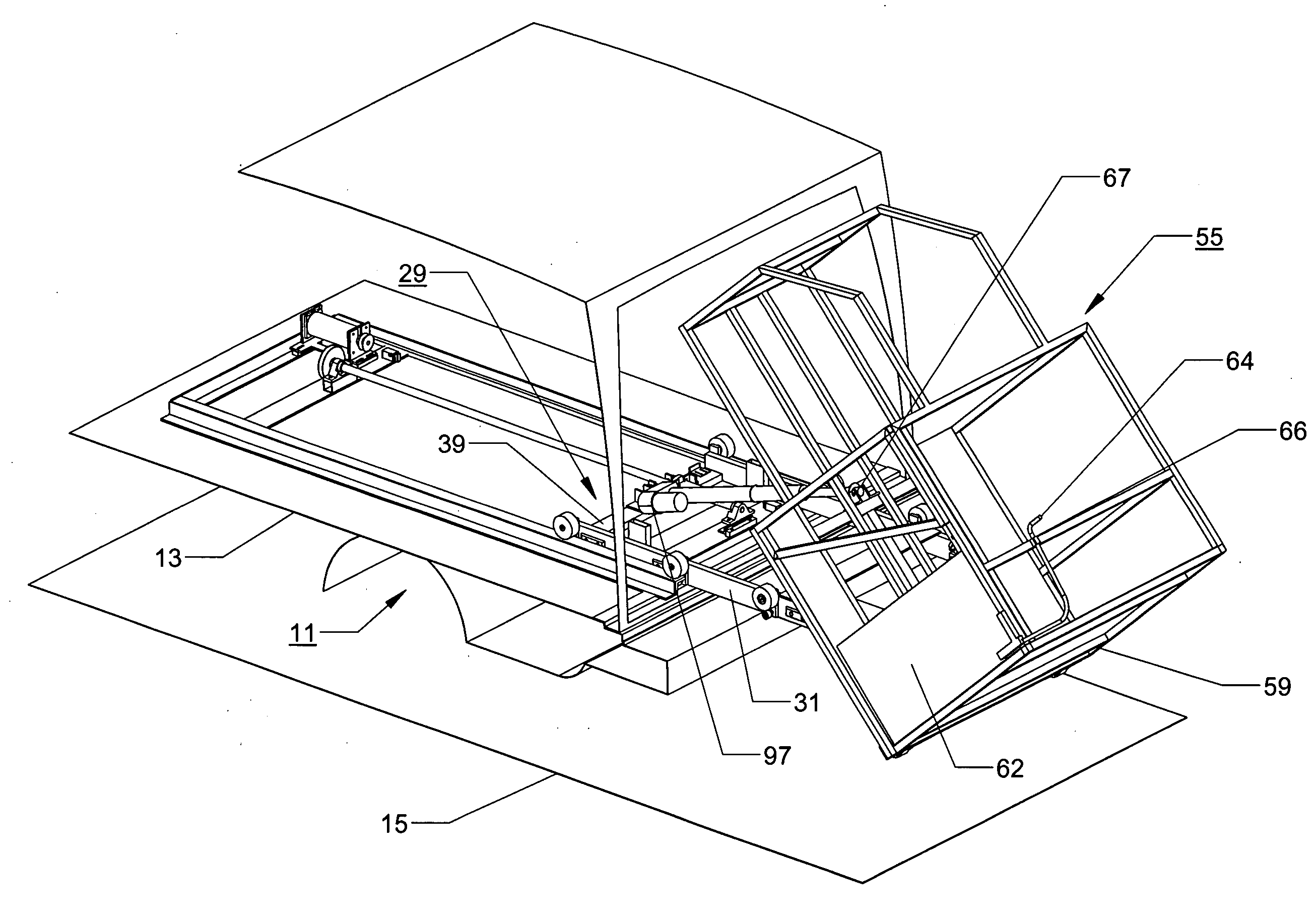
[0031] The cargo handling assembly of the present invention will now be described with reference to the accompanying drawings. The invention will be described in terms of its use with a mobile, overland vehicle such as a minivan, or standard-sized van of conventional design of the type having a cargo carrying region. However, it will be understood by those skilled in the art that the present cargo handling assembly could be utilized as well with other overland vehicles such as trucks, buses, and other similar vehicles.

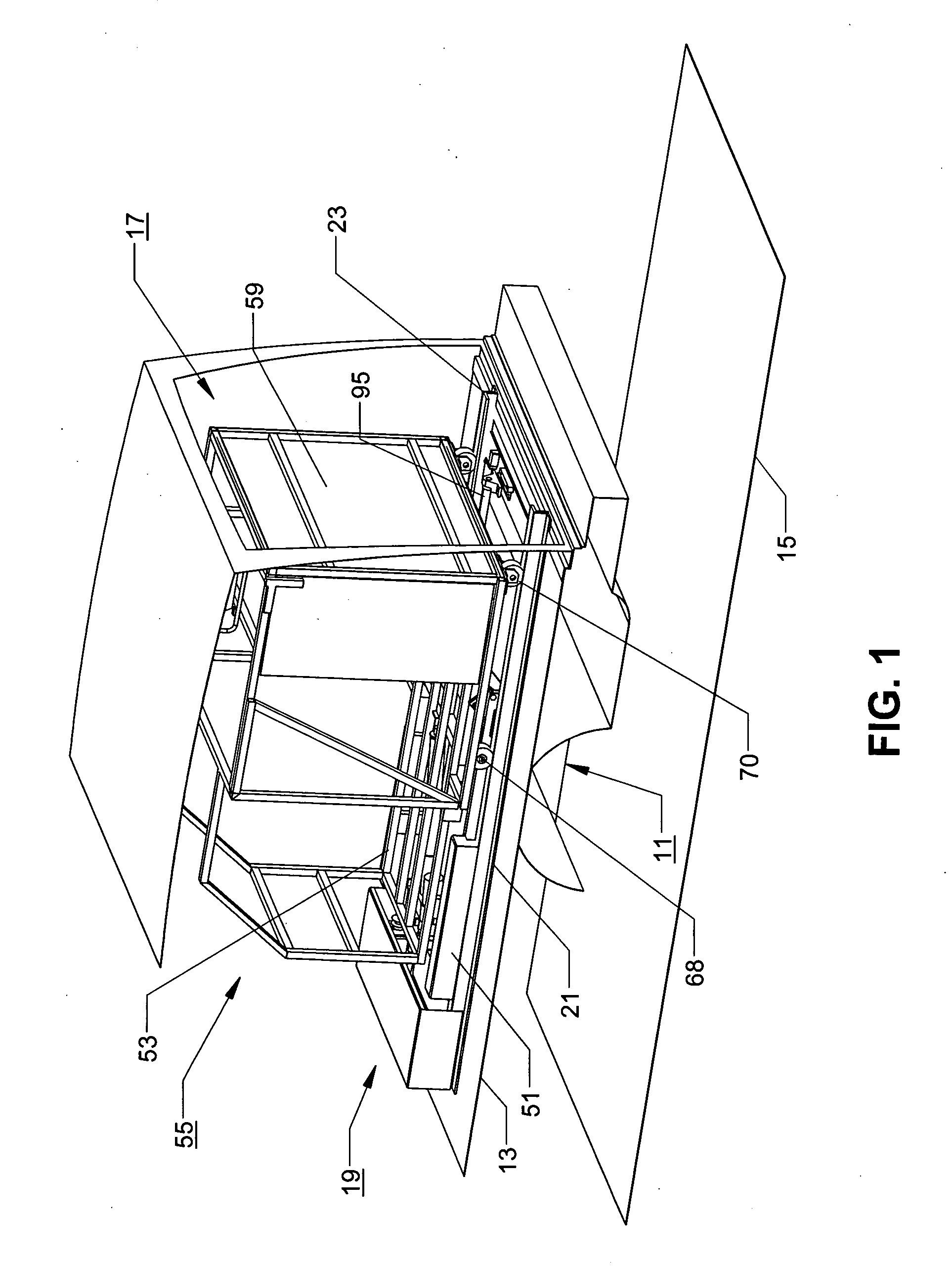
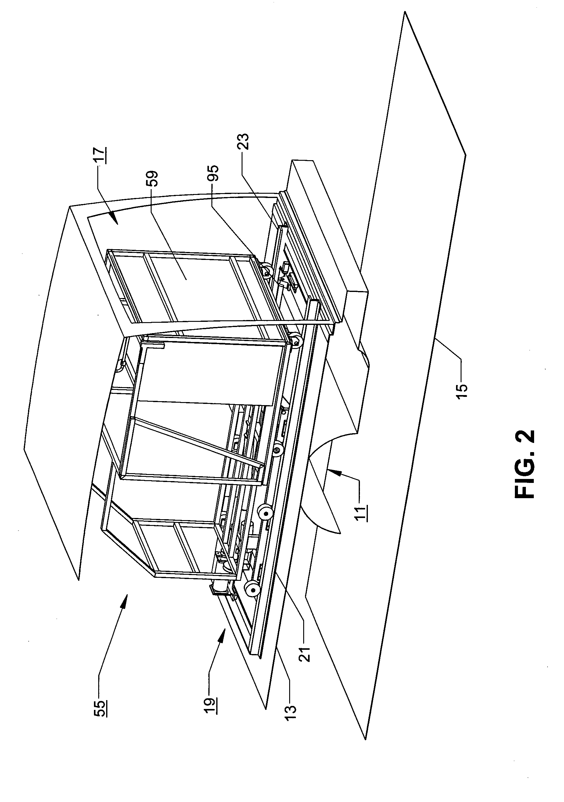
[0032] In FIGS. 1 and 2 of the drawings, only brief components parts of the conventional mobile vehicle are shown. Thus, there is shown an axle region 11 for containing earth engaging wheels and a floor region 13 which makes up the cargo carrying region of the vehicle. The floor region 13 is shown supported above the surrounding support surface 15, in this case the ground beneath the vehicle.

[0033] The typical overland vehicle has a pair of rear doors (not shown) whi...


PUM


Abstract

A cargo handling assembly for use with a mobile vehicle including a base frame which is capable of being mounted on the floor of the vehicle. The base frame has a pair of parallel spaced rail members. A carriage assembly having a pair of spaced parallel extension arms can be slidably advanced and retracted along the rail members. An opposing wheel arrangement, mounted on each extension arm, creates an opening for receiving a length of each parallel spaced rail member, whereby the carriage assembly is horizontally translatable along the length of the base frame by movement of the opposing wheels along the spaced rail members. A load cage is connected to the carriage by an actuator mechanism for rotating the load cage in an elliptical path about an rotational axis between a first position, where the cage is disposed in a substantially horizontal position and lies in nested relation relative to the base frame, and a second position, in which the cage is disposed in a substantially vertical position with respect to a surrounding support surface.

Description

BACKGROUND OF THE INVENTION [0001] 1. Field of the Invention [0002] The present invention relates to an equipment handling lift system which can be mounted in the cargo region of a standard-sized passenger van, a minivan, or other similarly designed vehicle, and which can load and unload bulky, heavy equipment safely and efficiently. [0003] 2. Description of Prior Art [0004] There are various examples in the prior art of cargo handling assemblies which are used for loading or unloading cargo from various overland vehicles such as railroad cars, automobiles, trucks and the like. In most cases, the devices of the prior art required fairly drastic modification of the overland vehicles in order to render the devices operational. Additionally, the prior art devices tended to be unduly complicated in design and cumbersome in nature, making the designs somewhat expensive to manufacture and difficult to install and maintain. [0005] Certain of the prior art designs, while acceptable for spec...

Claims


Application Information

Patent Timeline
IPC IPC(8): B60P1/64
CPCB60P1/4407B60P1/6427B60P1/4442
Inventor WARTHAN, JERRY G.
Owner WARTHAN JERRY G
Why Eureka
Try Eureka