Rotatable pivot mount for fans and other appliances

a technology for rotating pivots and fans, applied in the field of assembly, can solve the problems of gears increasing the difficulty in making adjustments, gear teeth reducing the precision of adjustments, etc., and achieve the effects of reducing the amount of force required, increasing the stability of the fan, and reducing the probability of the fan being moved out of position

Active Publication Date: 2007-07-19
HELEN OF TROY LIMITED
View PDF11 Cites 135 Cited by
  • Summary
  • Abstract
  • Description
  • Claims
  • Application Information

AI Technical Summary

Benefits of technology

[0006]The present invention is directed to a pivot assembly that can be used with various appliances. The pivot assembly provides three degrees of freedom when positioning the appliance. The pivot may be used, for example, with a fan that is mounted on a base such that the direction of the airflow generated can be adjusted about all three coordinate axes by manipulating a single rotatable pivot mount. Any adjustments to the positioning of the rotatable pivot mount are maintained by the friction within the rotatable pivot mount. The ability to direct airflow through the manipulation of a single rotatable pivot mount provides a fast adjustment and allows for more accurate airflow direction.
[0007]The fan assembly includes a base unit and an arm. The arm includes a mounting end to which the blower unit of the fan is detachably coupled. The opposite end of the arm is provided with a spherical cap which is received by the base unit. The base unit includes a bottom portion and a top portion. The top portion includes an opening through which the arm extends. The opening of the top portion is smaller than the diameter of the spherical cap of the arm thereby preventing the arm from being unintentionally detached from the base. The opening is shaped such that it is substantially flush with the outer surface of the spherical cap. The bottom portion of the base unit exerts a force against the spherical cap such that the friction between the spherical cap of the arm and the top portion of the base will maintain the positional adjustment made to the arm.
[0010]The fan blower may include a handle coupled to the blower by which the rotatable pivot mount may be adjusted and the fan direction altered. The handle should be positioned so that it will act as a lever when rotating the fan about any axis, thereby reducing the amount of force required to overcome the friction force created within the rotatable pivot mount.
[0011]In another embodiment of this invention the opening of the top portion of the base unit can act as a pivot guide for positioning the arm by preventing the fan from being adjusted to certain positions. If the fan is pivoted too far off the vertical axis, the center of gravity may extend beyond the support area provided by the base and the fan may become unstable and topple over. The shape of the pivot guide can be adjusted to prevent the fan from pivoting to a position where the center of gravity of the fan extends beyond the support area provided by the base.
[0012]The pivot guide also provides increased stability of the fan when adjusted to certain positions. The pivot guide can provide inlets in which the arm rests, thus complementing the support provided by the frictional force exerted by the bottom potion of the base unit. Thus, while the arm is positioned in one of the inlets provided by the pivot guide, if the assembly is disturbed by an external force, the added stability decreases the likelihood of the fan being moved out of position.
[0013]Additionally, the pivot guide may be detachable from the base unit, thus making the shape of the top portion opening modifiable. Because the shape of the opening serves a decorative purpose as well as the functional purpose described above, the decorative element can be enhanced by allowing a user to select a pivot guide to match any desired esthetic or visual appearance.

Problems solved by technology

However, the gear teeth decrease the precision of the adjustments since the teeth must properly mesh at predefined positions.
Also, the gears increase the difficulty in making the adjustments since the mount surfaces no longer smoothly glide as the mounting is rotated.

Method used


Image

  • Rotatable pivot mount for fans and other appliances
  • Rotatable pivot mount for fans and other appliances
  • Rotatable pivot mount for fans and other appliances

Examples


Embodiment Construction

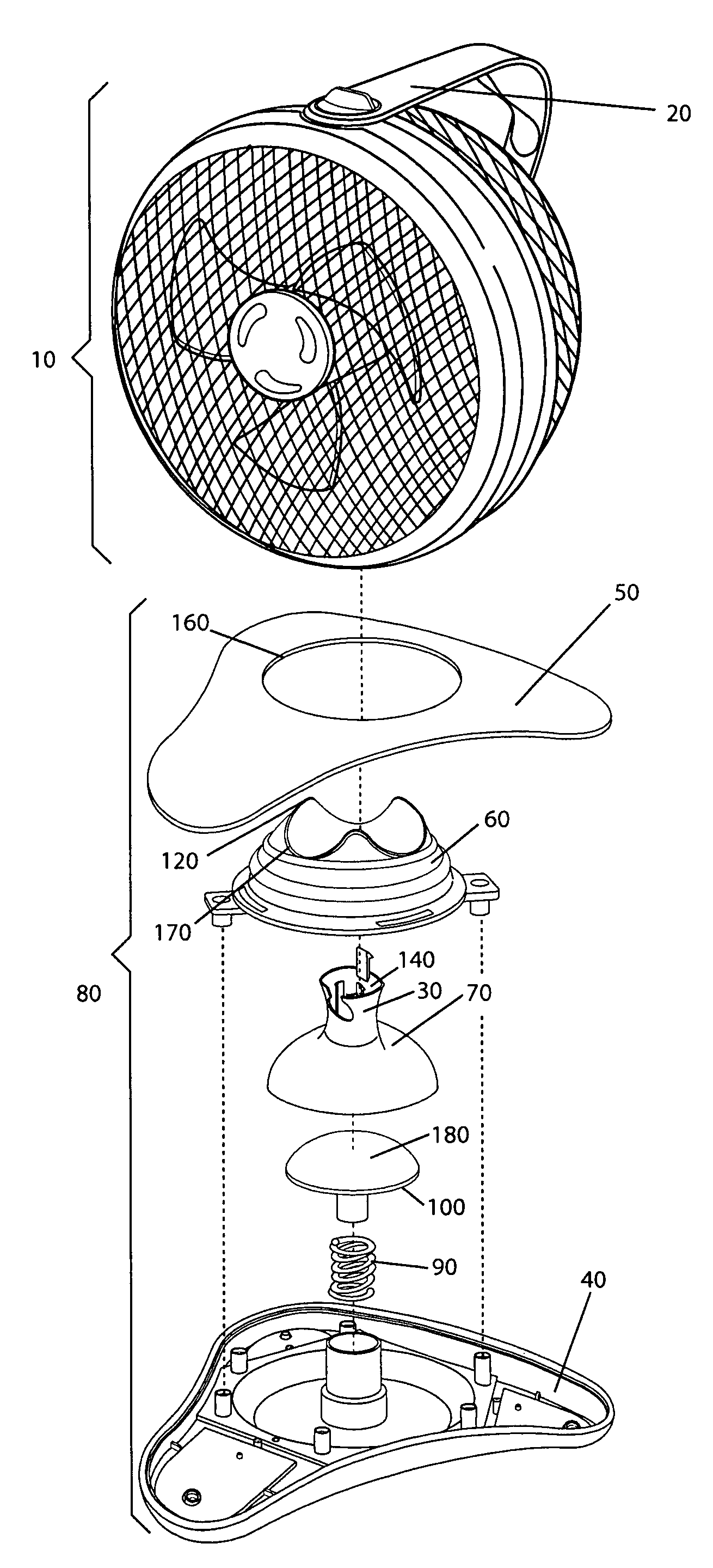
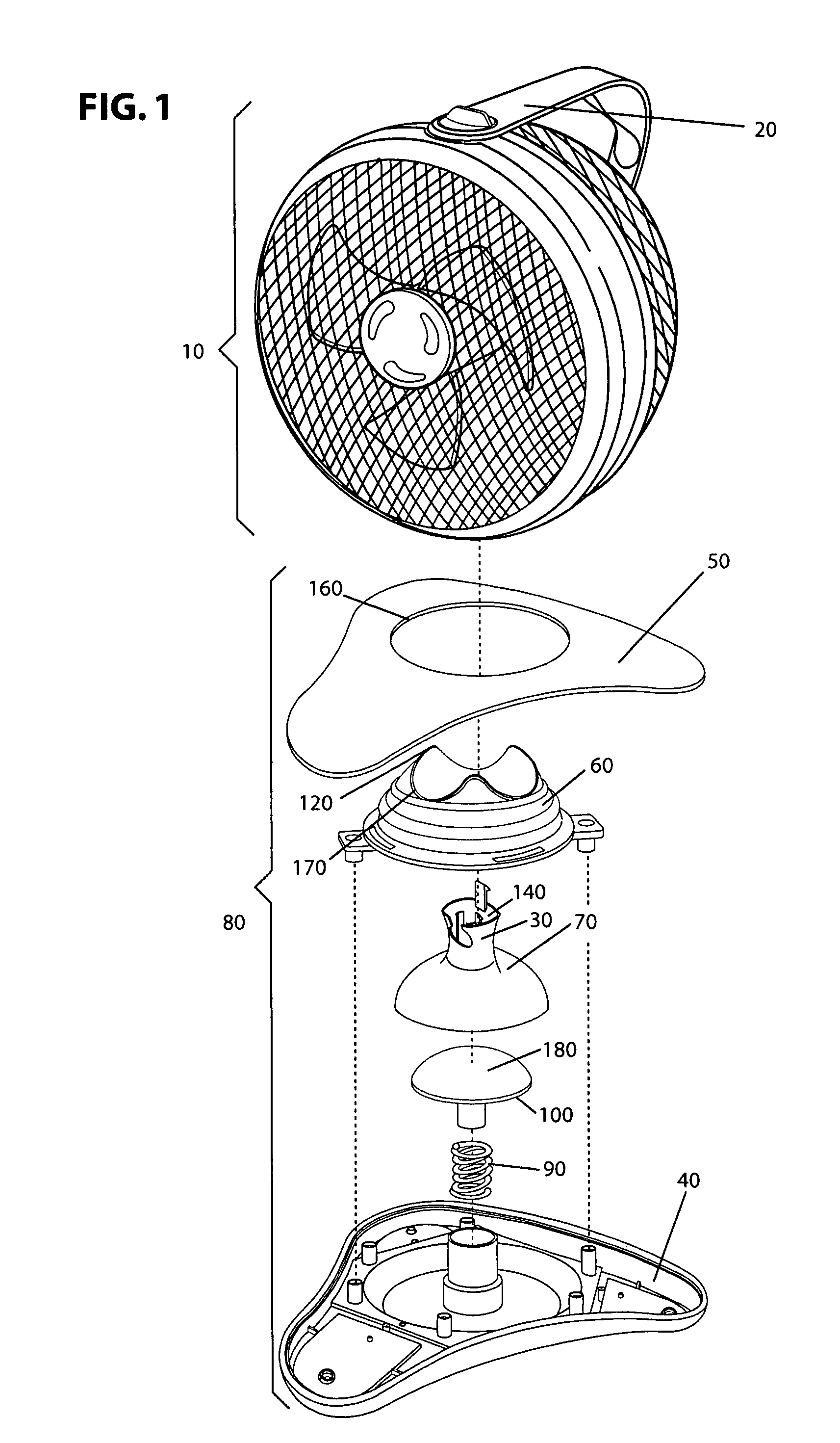
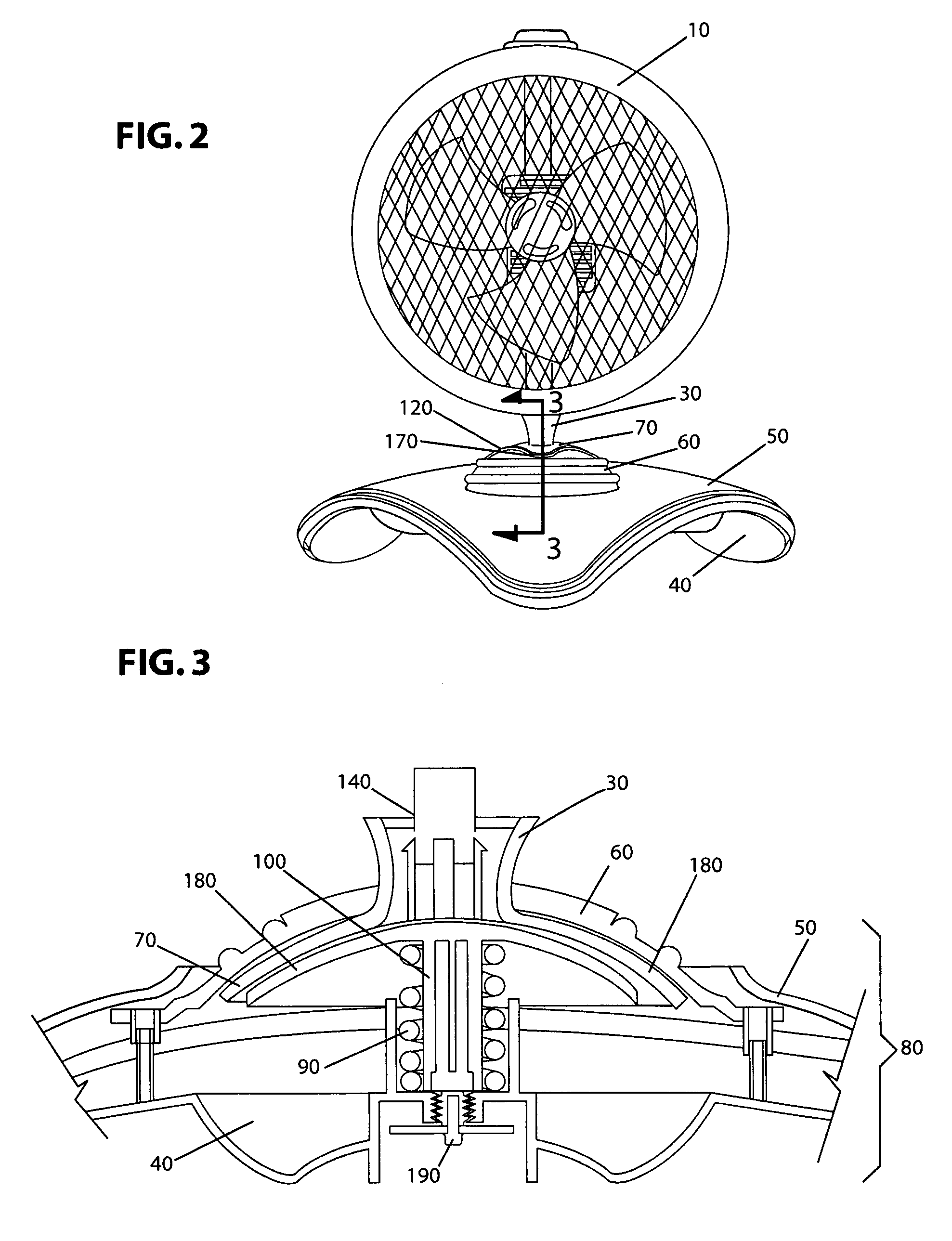
[0018]Referring now to the drawings the present invention is directed to a pivot mount assembly. The pivot may be used with almost any appliance, including a mirror, fan, or heater. By way of illustration, the pivot mount is discussed in conjunction with a fan assembly that allows the airflow generated to be adjusted along three axes by manipulating a single rotatable pivot mount. Any adjustments to the positioning of the rotatable pivot mount are maintained by the continuous friction at the rotatable pivot mount. The ability to direct airflow in one or more dimensions through the manipulation of a single rotatable pivot mount provides a fast adjustment and allows for more accurate airflow direction.

[0019]Referring now to FIGS. 1-3, the fan assembly includes a base unit 80 and an arm 30. The arm 30 includes a pivot end having a spherical cap 70 and a receiving end 140 to which the blower 10 can be detachably coupled. An axis of the arm is defined by the pivot end and the receiving e...


PUM


Abstract

A pivot assembly that can be used with various appliances. The pivot assembly provides up to three degrees of freedom when positioning the appliance. The pivot may be used, for example, with a fan that is mounted on a base such that direction of the airflow generated can be adjusted about three coordinate axes by manipulating a single rotatable pivot mount. The fan assembly includes a base unit and an arm to which an appliance may be detachably coupled. The opposite end of the arm is provided with a spherical cap which is received by the base unit. Any adjustments to the positioning of the rotatable pivot mount are maintained by the friction within the rotatable pivot mount. Additionally, the pivot mount may include a pivot guide to restrict the degree of rotation about the pivot, thereby increasing stability.

Description

FIELD OF THE INVENTION[0001]The invention relates to an assembly of the type which can be positioned to change the direction of an appliance in the horizontal and vertical directions.BACKGROUND OF THE INVENTION[0002]Directionally adjustable fans have long been known. Such fans are useful when it is desirable to direct the airflow from the fan in a specific direction without moving the base of the fan.[0003]Directionally adjustable fans that are capable of pivoting about both the vertical axis and the horizontal axis are typically designed with two pivot mechanisms—one for each axis. One type of pivot mechanism which allows adjustment of the vertical direction of the airflow includes coupling the fan assembly to rotatable mounts at each of the two ends of the diameter of the fan assembly forming an axis of rotation that is parallel to the floor of the base of the fan. Alternatively, the fan assembly is coupled to an arm which is rotatably mounted to the base, thereby allowing the fan...

Claims


Application Information

Patent Timeline
Patent Type & Authority Applications(United States)
IPC IPC(8): F04D25/08
CPCF04D29/601F04D25/08
Inventor RUSSAK, STEPHENDEMORE, ANTHONYVORDENBERG, STEVENLAI, ANTHONYRIZZARI, ROBERTBOSSA, DAVIDHUANG, SIMONQUI, PEACHEN
Owner HELEN OF TROY LIMITED
Why Eureka
Try Eureka