Method and apparatus for making bags

Active Publication Date: 2007-07-19
CMD CORP
View PDF30 Cites 45 Cited by
  • Summary
  • Abstract
  • Description
  • Claims
  • Application Information

AI Technical Summary

Benefits of technology

[0029] A second seal is formed such that the weakened area is adjacent and between the first and second seals in another embodiment. The distance fr

Problems solved by technology

Ideally, the perforation is close to the seal to reduce waste, although this is difficult in practice.
The web between the pair of seals is wasted.
Thus, the pair of seals should be close to one another to reduce waste, although this is also difficult in practice.
Sensing the seal has proven to be difficult.
If the perforation is placed too close to one side seal, then the seal may be cut off, rendering the bag useless.
Because sensing the seal is difficult, much waste is generated in bag making, or bags are ruined.
The wasted web, (i.e. the web between a seal and the adjacent perforation), or the web used to make the ruined bag, can be very costly, particularly for high speed bag machines where the number of bags made per hour is great.
An

Method used


Image

  • Method and apparatus for making bags
  • Method and apparatus for making bags
  • Method and apparatus for making bags

Examples


Embodiment Construction

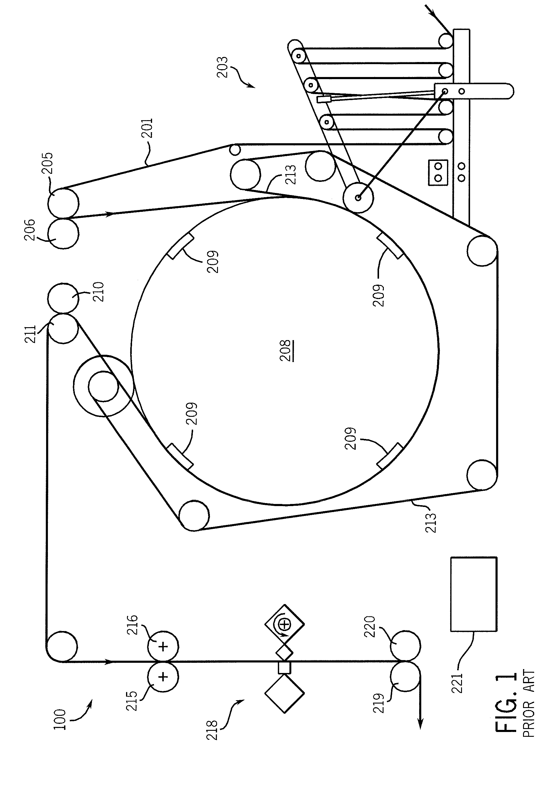
[0059] While the present invention will be illustrated with reference to a particular bag machine, it should be understood at the outset that the invention can also be implemented with other machines, and using other components. Bag machine, as used herein, includes a machine used to make bags such as draw tape bags, non-draw tape bags, and other bags. Any input section (unwinds and dancers, e.g.) and any output section (winders, folders, e.g.) may be used with the present invention.

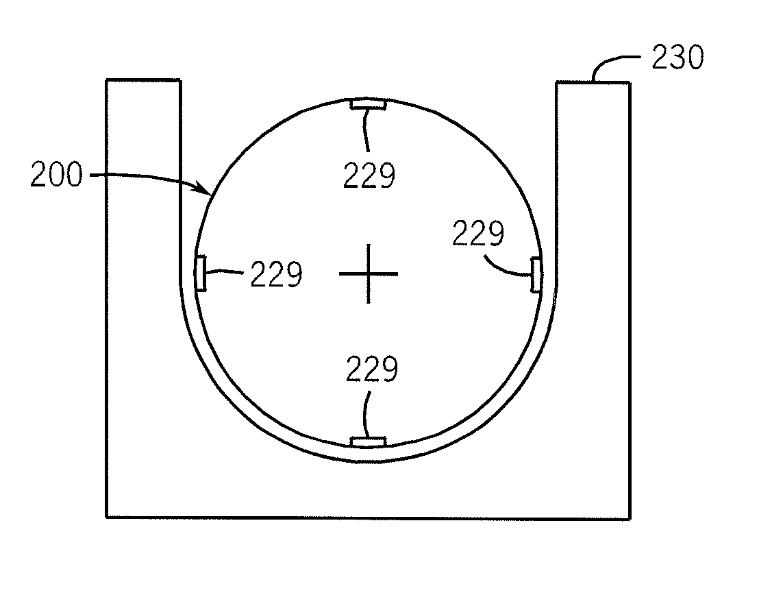
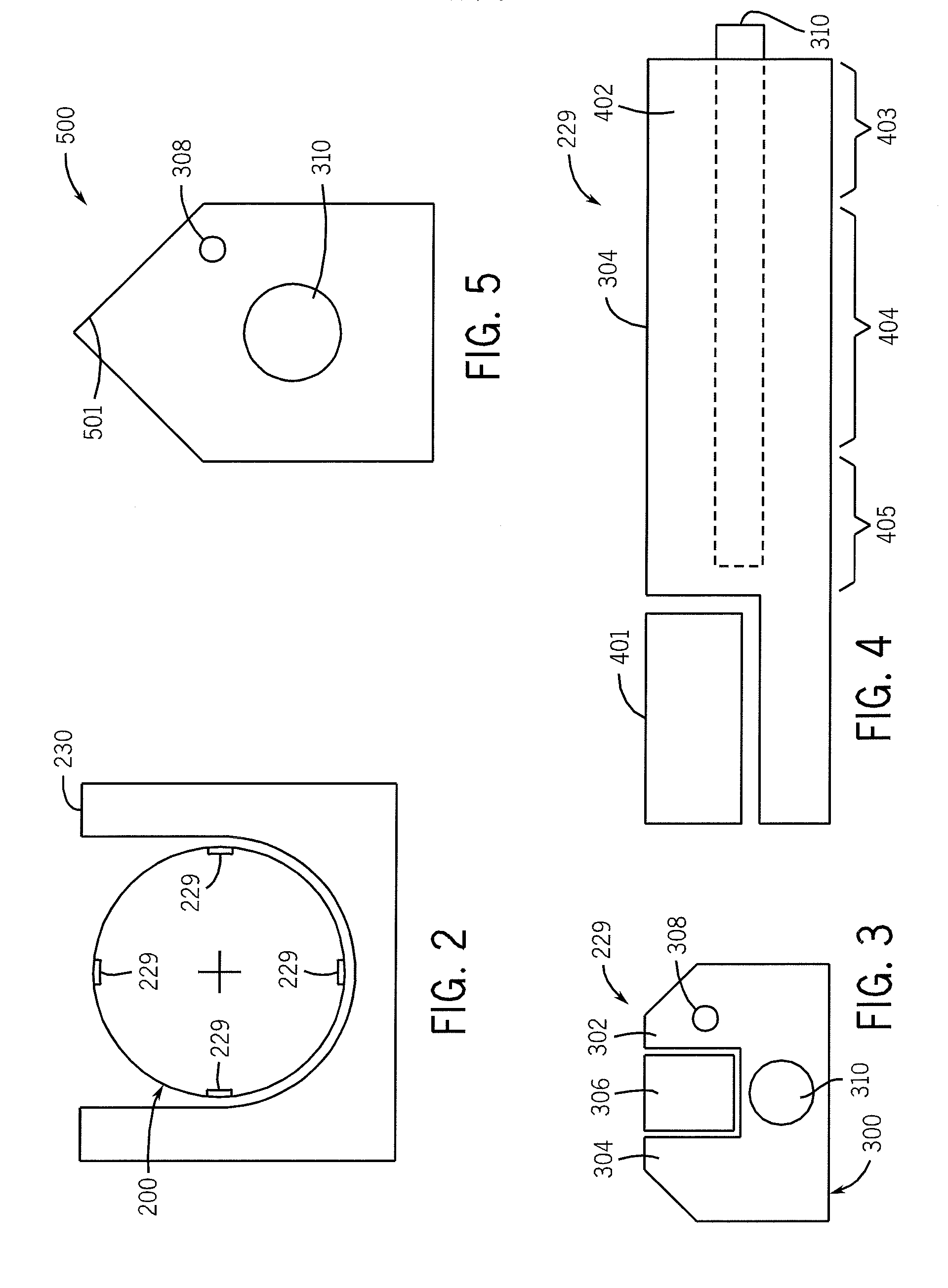
[0060] Generally, the present invention provides for a rotary bag machine with an input section, a drum section, and an output section. A perforation or line of weakness is formed on the rotary drum, for at least part of the time the seal is being formed. For example, on a rotary bag machine the web might be in contact with the drum for about one-half of the drum cycle, and the perforator formed in one quarter of the drum cycle. The seal bar includes a sealing zone and applies heat as the drum rotates, ...


PUM

PropertyMeasurementUnit
Fractionaaaaaaaaaa
Fractionaaaaaaaaaa
Distanceaaaaaaaaaa

Abstract

A machine and method for making bags is described and includes a web traveling from an input section to a rotary drum, to an output section. The rotary drum includes at least one seal bar, having a first sealing zone, and an adjacent weakening zone. The weakening zone may be a heated perforator, includes a heating wire, or be disposed to create an auxiliary sealed area. The heating wire can have, connected thereto, a source of power that is at an adjustable voltage or magnitude, and/or pulsed, and/or a feedback loop. The heating wire may be an NiCr wire and make intermittent contact with the web and be disposed in an insert. The weakening zone may create a line of weakness that is uniform or varies in intensity, is a separating zone, or includes a heat film, a toothed blade, a row of pins, a source of air, or a source of vacuum. The sealing zones may include temperature zones, cartridge heaters, cooling air, or heated air, or a source of ultrasonic, microwave or radiative energy.

Description

FIELD OF THE INVENTION [0001] The present invention relates generally to the art of bag making. More specifically, it relates to bag making machines and a bag making method that create bags from a film or web and form seals and perforations or a line of weakness separating adjoining bags made from the web. BACKGROUND OF THE INVENTION [0002] There are many know bag machines. One style is a rotary drum machine. Rotary drum machines are well known, and a detailed description may be found in U.S. Pat. Nos. 6,117,058, 4,934,993, 5,518,559, 5,587,032 and 4,642,084 (each of which is hereby incorporated by reference). [0003] A detailed description of the operation of rotary bag machines may be found in the patents above, but their general operation may be see with respect to FIG. 1. A prior art rotary bag machine 100 continuously processes a web 201 using a dancer assembly 203, a pair of drum-in rolls 205 and 206 (203-206 are part of an input section), a sealing drum 208, a pair of drum-out...

Claims


Application Information

Patent Timeline
IPC IPC(8): B31B1/28B31B50/10B31B50/16B31B50/28B31B50/64B31B70/00
CPCB29C65/10B29C65/14B29C65/1412B29C65/1425B29C65/1467B29C65/16B29C65/18B29C65/38B29C65/7412B29C65/7433B29C65/7437B29C65/7451B29C65/7453B29C65/7457B29C66/0042B29C66/232B29C66/3472B29C66/348B29C66/349B29C66/7352B29C66/80B29C66/8122B29C66/81262B29C66/81267B29C66/818B29C66/83511B29C66/8511B29C66/91231B29C66/919B29C66/939B29C66/949B29C2035/0822B29C2793/0045B29K2023/0625B29K2905/02B31B1/74B31B19/14B31B27/00B31B2201/61B31B2219/028B31B2219/14B31B2219/924B31B2237/60B31B1/10B29C65/1496B29C65/222B29C65/305B29C65/229B29C65/7847B29C66/83417B29C66/83433B29C66/83517B29C65/1696B29C66/91653B29C66/81417B29C66/81419B29C66/81427B29C66/1122B29C66/43B29C66/91423B29C66/93451B29C66/81812B29C66/91212B29C66/91315B29C66/962B29C66/961B29C66/91651B29C66/91421B29C66/91431B29C66/91631B29C66/91641B29C66/81431Y10T156/1054Y10T156/1313B29K2827/18B29C65/00B29C66/9141B29K2995/007B29C66/81264B29C66/81241B29C66/71B31B2160/10B31B70/14B31B2155/00B31B2160/20B31B50/741B31B70/024B31B70/946B31B2155/003Y10T83/9408Y10T83/0414Y10T83/293Y10T83/9292B31B70/00B31B70/146B29K2909/08B29L2031/7128
Inventor SELLE, PAULRADTKE, KENNETH C.SAUDER, CHARLES H.JOHNSON, PAUL A.WHITE, CHRISTOPHER LEEJOHNSON, ARVID R.PRELLWITZ, GREGORY T.STICKNEY, MICHAEL J.JANSEN, THOMAS C.SAUCIER, CHRISTOPHER A.LEITZKE, TERRY L.SCHMOLL, BRADLEY J.
Owner CMD CORP
Why Eureka
Try Eureka