Supercharge Your Innovation With Domain-Expert AI Agents!

Torque converter

a torque converter and converter technology, applied in the direction of fluid couplings, gearings, couplings, etc., can solve the problems of deteriorating performance of torque converters, and achieve the effects of improving efficiency, increasing the capacity coefficient and increasing the torque ratio in the high-speed ratio rang

Inactive Publication Date: 2007-07-26
EXEDY CORP
View PDF5 Cites 7 Cited by
  • Summary
  • Abstract
  • Description
  • Claims
  • Application Information

AI Technical Summary

Benefits of technology

[0005] It is an object of the present invention to reduce deterioration in the fluid operation performance of the torque converter having a torus that is further flattened.
[0009] In this torque converter, the outlet radius of the turbine can be shortened, so that torque ratio in a high-speed ratio range becomes higher, thereby improving the efficiency. In addition, the radius of the outlet and inlet of the stator can be shortened, so that the capacity coefficient in the high-speed ratio range becomes higher.
[0017] In the torque converter according to the present invention, the fluid driving performance is unlikely to deteriorate, although the torus is further flattened.

Problems solved by technology

However, if the torus is further flattened, the performance of the torque converter may deteriorate.

Method used


Image

  • Torque converter
  • Torque converter
  • Torque converter

Examples


Embodiment Construction

(1) Structure

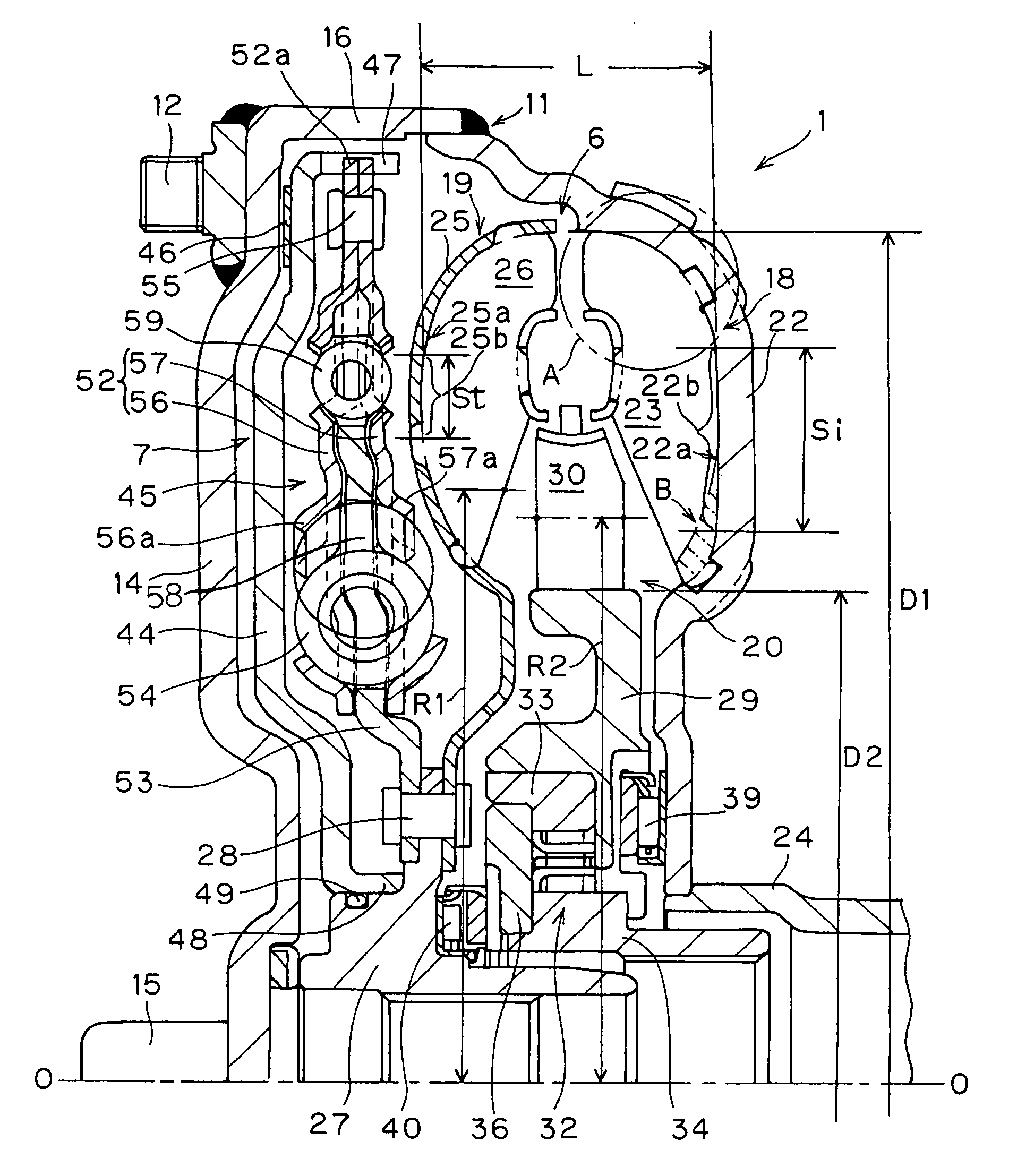
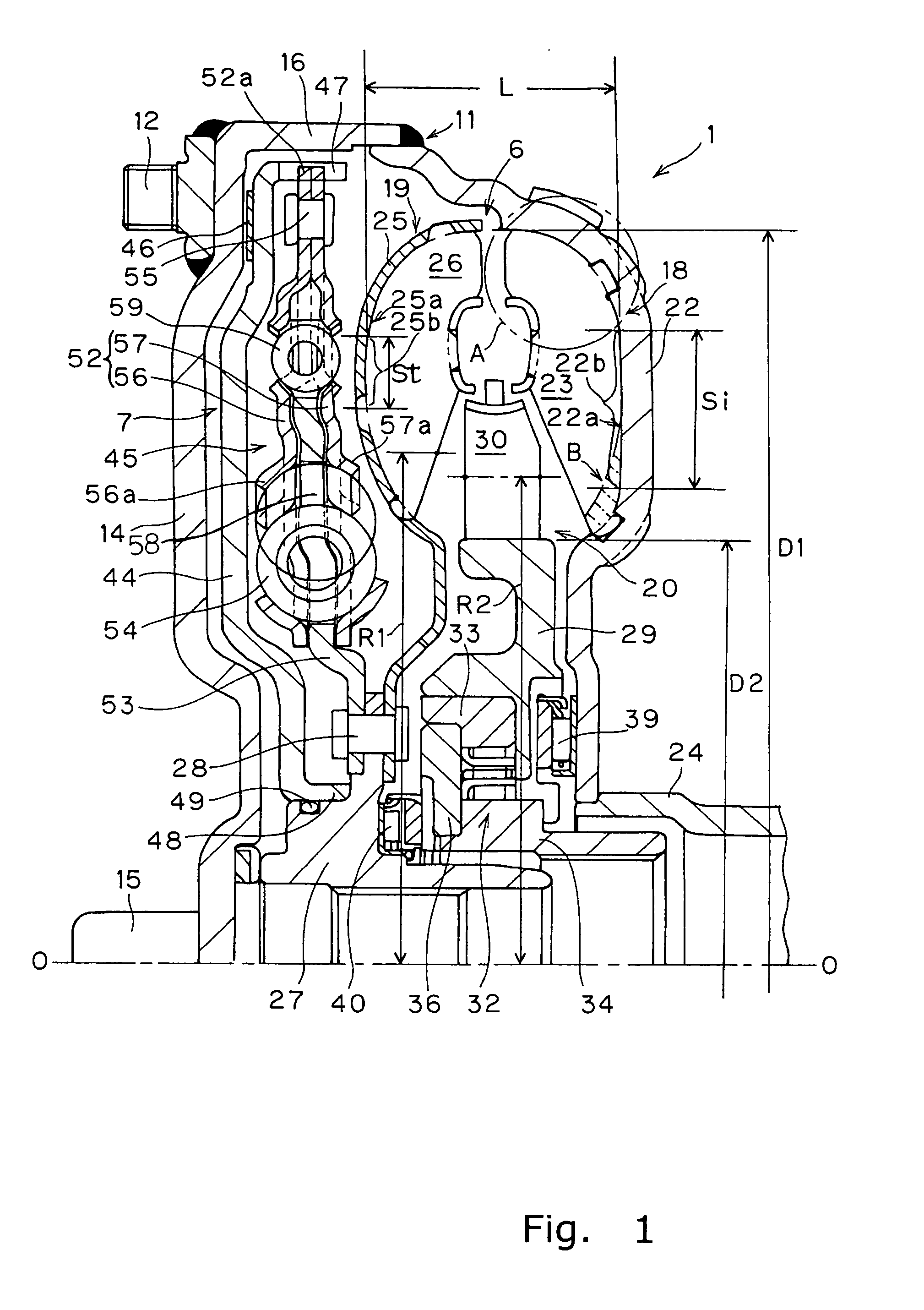
[0029]FIG. 1 is a longitudinal cross sectional diagram of a torque converter 1 in which an embodiment of the present invention is employed. The torque converter 1 is a device to transmit torque from a crankshaft of the engine to an input shaft of the transmission (not shown). The engine (not shown) is located on the left side of FIG. 1, and the transmission (not shown) is located on the right side of FIG. 1. The line O-O shown in FIG. 1 is a rotational axis of the torque converter 1.

[0030] The torque converter 1 is mainly made of a fluid operating chamber (torus) 6 having a torus shape formed by three kinds of vane wheels including an impeller 18, a turbine 19, and a stator 20. The torque converter 1 also includes a lock-up device 7.

1) Fluid Operating Chamber

[0031] The front cover 14 is a disc-like member that is located adjacent a flexible plate. A center boss 15 by welding is fixed to a radially inner portion of the front cover 14. The center boss 15 is an axial...


PUM


Abstract

A torque converter 1 is a device for transmitting torque by fluid, and includes a front cover 14, an impeller 18, a turbine 19, and a stator 20. The impeller 18, the turbine 19 and the stator 20 constitute a fluid operating chamber 6 having a torus shape. Flattening (L / D1) is less than or equal to 0.18, wherein D1 is an outer diameter of the fluid operating chamber 6 and L is the axial direction length of the fluid operating chamber 6. In the impeller shell 22, a surface 22a on which the impeller blades 23 are fixed has an impeller straight portion 22b showing a straight line in a cross section. In the turbine shell 25, a surface 25a on which the turbine blades 26 are fixed has a turbine straight portion 25b showing a straight line in a cross section.

Description

TECHNICAL FIELD [0001] The present invention is related to a torque converter, particularly to a torque converter that is extremely flattened. BACKGROUND ART [0002] A torque converter includes a torus having three types of vane wheels (an impeller, a turbine, and a stator) and serves to transmit torque by fluid in the torus. The impeller forms a fluid chamber filled with operating oil with the front cover. The impeller is mainly made of an annular impeller shell, a plurality of impeller blades fixed to an inner surface of the impeller shell, and an annular impeller core fixed to the inner ends of the impeller blades. The turbine is disposed in the interior of the fluid chamber opposing the impeller in the axial direction. The turbine is mainly made of an annular turbine shell, a plurality of turbine blades fixed to a surface of the turbine shell facing the impeller, and an annular turbine core fixed to the inner ends of the turbine blades. A radially inner portion of the turbine she...

Claims


Application Information

Patent Timeline
IPC IPC(8): F16D33/00F16H41/24F16H45/02F16H41/26
CPCF16H41/26F16H2045/0294F16H2045/0226F16H45/02F16H41/24
Inventor FUKUNAGA, TAKAOKUNISAKI, YASUNORI
Owner EXEDY CORP
Features
  • R&D
  • Intellectual Property
  • Life Sciences
  • Materials
  • Tech Scout
  • Unparalleled Data Quality
  • Higher Quality Content
  • 60% Fewer Hallucinations
Learn More