Segmented effusion cooled gas turbine engine combustor

a technology of gas turbine engines and combustor cooling, which is applied in the direction of machines/engines, efficient propulsion technologies, light and heating apparatus, etc., can solve the problems of affecting the service life of combustor, affecting and suffering certain drawbacks, so as to improve the cooling efficiency of combustor

Active Publication Date: 2007-07-26
HONEYWELL INT INC
View PDF13 Cites 56 Cited by
  • Summary
  • Abstract
  • Description
  • Claims
  • Application Information

AI Technical Summary

Benefits of technology

[0007] The present invention provides a combustor effusion cooling mechanism that improves combustor cooling efficiency. In one embodiment, and by way of example only, a gas turbine engine combustor includes an inner liner, an outer liner, a dome assembly, and two or more sets of effusion cooling holes. The inner liner has an inner surface, an outer surface, an upstream end, and a downstream end, and extends in an axial direction between the upstream and downstream ends. The outer liner extends in the axial direction and has an inner surface, an outer surface, an upstream end, and a downstream end. The outer liner is spaced apart from, and at least partially surrounds, the inner liner. The dome assembly is coupled between the upstream ends of the inner and outer annular liners to define a combustion chamber between the inner liner outer surface and the outer liner inner surface. The two or more sets of effusion cooling holes extend through the outer liner between the outer liner outer and inner surfaces. Each set of effusion cooling holes includes one or more initial rows of effusion cooling holes, one or more final rows of effusion cooling holes disposed downstream of the one or more initial rows, and a plurality of interposed rows of effusion cooling holes disposed between the initial and final rows. Each effusion cooling hole in the one or more initial rows is disposed at a tangential angle of between about 70° and about 90° relative to the axial direction. Each effusion cooling hole in the one or more final rows is disposed at a tangential angle of between about 0° and about 20° relative to the axial direction. Each effusion cooling hole in each of the interposed rows is disposed at a tangential angle, relative to the axial direction, that is less than the tangential angle of the effusion cooling holes in the one or more initial rows and greater than the tangential angle of the effusion cooling holes in the one or more final rows.
[0009] In yet another exemplary embodiment, a gas turbine engine includes a compressor, a turbine, and a combustor with an effusion cooling mechanism that improves combustor cooling efficiency.

Problems solved by technology

Such high temperatures can adversely impact the service life of a combustor.
Although effusion cooling is generally effective, it does suffer certain drawbacks.
Such cooling augmentation can complicate the construction of combustor and increase overall size, weight, and / or costs.

Method used


Image

  • Segmented effusion cooled gas turbine engine combustor
  • Segmented effusion cooled gas turbine engine combustor
  • Segmented effusion cooled gas turbine engine combustor

Examples


Embodiment Construction

[0016] The following detailed description of the invention is merely exemplary in nature and is not intended to limit the invention or the application and uses of the invention. Furthermore, there is no intention to be bound by any theory presented in the preceding background of the invention or the following detailed description of the invention. In this regard, it will be appreciated that the described embodiment is not limited to use in conjunction with a particular type of turbine engine or with a particular type of combustor. Thus, although the present embodiment is, for convenience of explanation, depicted and described as being implemented in a multi-spool turbofan gas turbine jet engine, and with an annular combustor, it will be appreciated that it can be implemented in various other types of turbines, with other types of combustors, and in various other systems and environments.

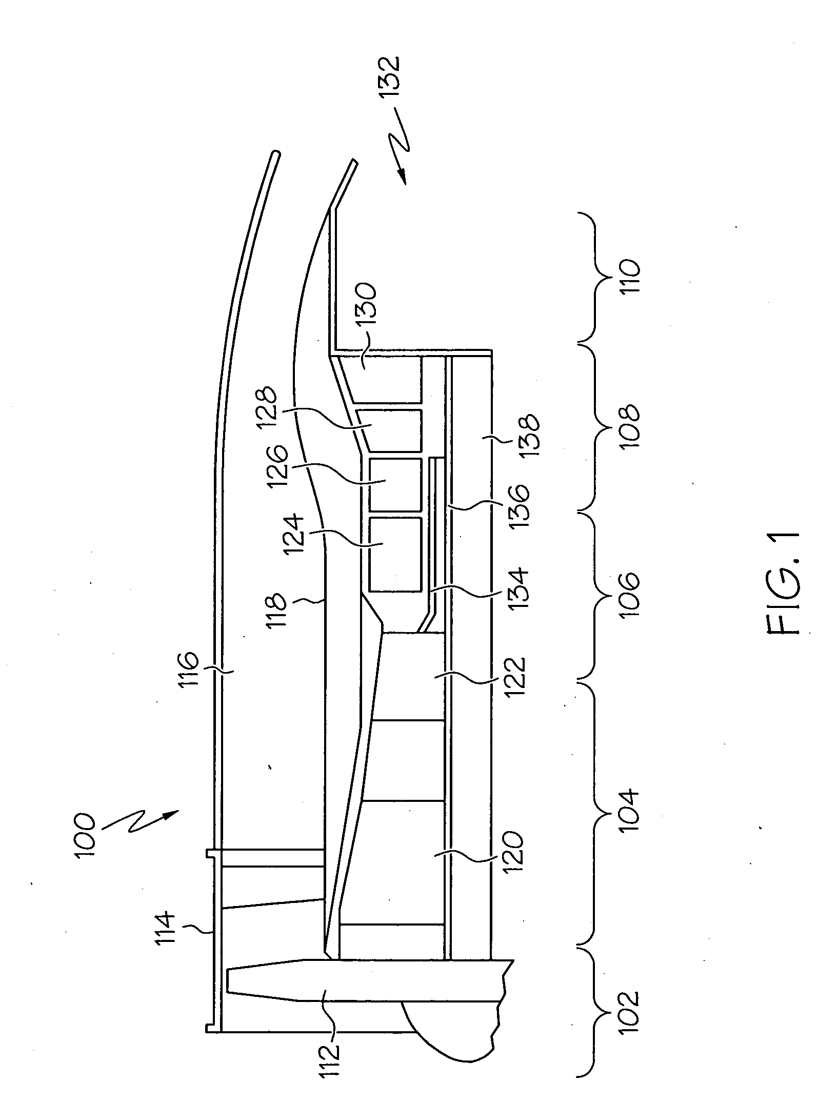
[0017] An exemplary embodiment of a multi-spool turbofan gas turbine jet engine 100 is depicted ...


PUM


Abstract

A combustor includes two or more sets of effusion cooling holes that extend through the inner and outer liners. Each set of effusion cooling holes includes one or more initial rows of effusion cooling holes, one or more final rows of effusion cooling holes disposed downstream of the one or more initial rows, and a plurality of interposed rows of effusion cooling holes disposed between the initial and final rows. Each effusion cooling hole is disposed at a tangential angle relative to an axial line. The tangential angle of the effusion cooling holes in each set of effusion cooling holes gradually transitions from a substantially transverse tangential angle in each initial row to a substantially axial tangential angle in each final row.

Description

TECHNICAL FIELD [0001] The present invention relates to gas turbine engines and, more particularly, to a gas turbine engine combustor effusion cooling mechanism that improves combustor cooling efficiency. BACKGROUND [0002] A gas turbine engine may be used to power various types of vehicles and systems. A particular type of gas turbine engine that may be used to power aircraft is a turbofan gas turbine engine. A turbofan gas turbine engine may include, for example, five major sections, a fan section, a compressor section, a combustor section, a turbine section, and an exhaust section. The fan section is positioned at the front, or “inlet” section of the engine, and includes a fan that induces air from the surrounding environment into the engine, and accelerates a fraction of this air toward the compressor section. The remaining fraction of air induced into the fan section is accelerated into and through a bypass plenum, and out the exhaust section. [0003] The compressor section raise...

Claims


Application Information

Patent Timeline
Patent Type & Authority Applications(United States)
IPC IPC(8): F23R3/04
CPCF23R3/002Y02T50/675F23R2900/03041F23R3/06Y02T50/60
Inventor SCHUMACHER, JURGEN C.ZUPANC, FRANK J.DUDEBOUT, RODOLPHE
Owner HONEYWELL INT INC
Why Eureka
Try Eureka