Liquid-condition detection sensor

a technology of liquid condition and detection sensor, which is applied in the direction of liquid/fluent solid measurement, instruments, machines/engines, etc., can solve the problems of short circuit between the holder tube, risk of contact, and worker erroneously mixing light oil or water

Inactive Publication Date: 2007-07-26
NGK SPARK PLUG CO LTD
View PDF7 Cites 14 Cited by
  • Summary
  • Abstract
  • Description
  • Claims
  • Application Information

AI Technical Summary

Benefits of technology

[0048]In the case where the liquid-condition detection sensor of the present invention is used in an exhaust gas purification apparatus mounted in an automobile or the like, even when this liquid-condition detection sensor is subjected to vibration or impact associated with driving or the like, continued use of the liquid-condition detection sensor is possible without incurring a short circuit or cracking.

Problems solved by technology

Also, a worker may erroneously mix light oil or water in the tank.
However, an assembled state of the above configuration may involve a risk of contact and a resultant short circuit between the holder tube and the terminal member.
Also, there may be a risk of contact and a resultant short circuit between the holder tube and the sensor element or a risk of cracking or the like in the sensor element.
In the case where a plurality of terminal members are present, there may be a risk of contact and a resultant short circuit between the terminal members.
Furthermore, vibration or impact during actual use vibrates the sensor element, the terminal member, the lead wire, and the like and consequently generates stress in a connection between the lead wire and the terminal member or a connection between the terminal member and the sensor element.
Such vibration or impact potentially induces cracking or a like problem in these connections or portions of the terminal member and the sensor element in the vicinity of the connections.

Method used


Image

  • Liquid-condition detection sensor
  • Liquid-condition detection sensor
  • Liquid-condition detection sensor

Examples


Embodiment Construction

[0089]An embodiment of a liquid-condition detection sensor according to the present invention will be described with reference to the drawings. However, the present invention should not be considered as being limited thereto.

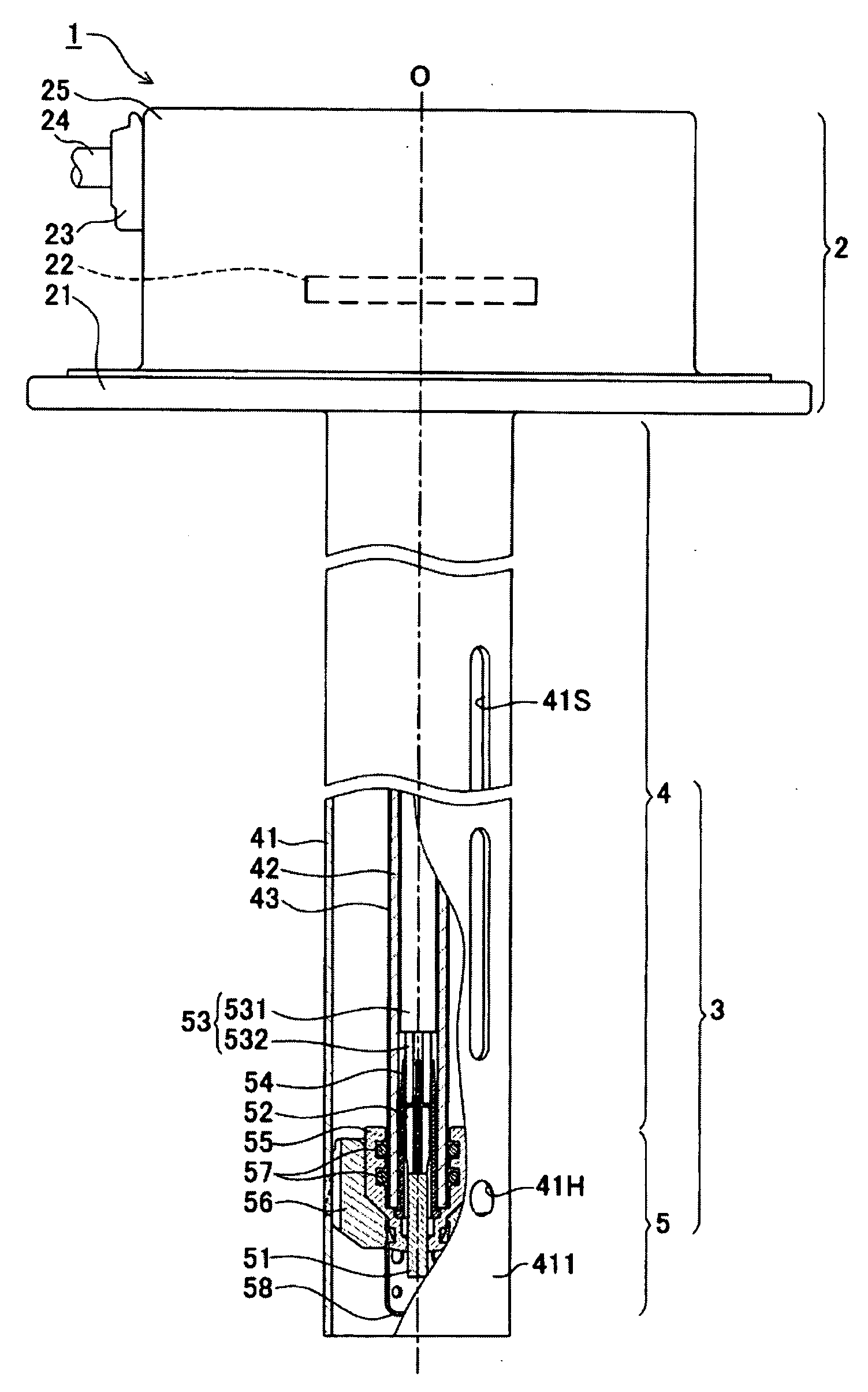
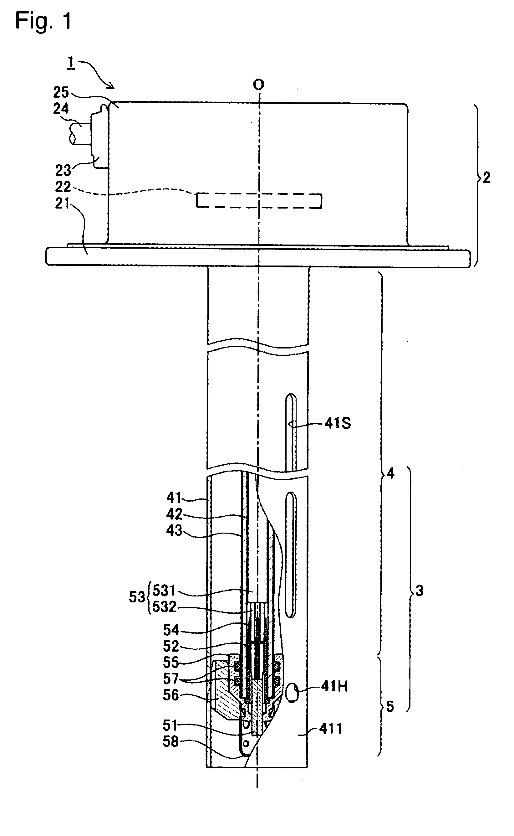
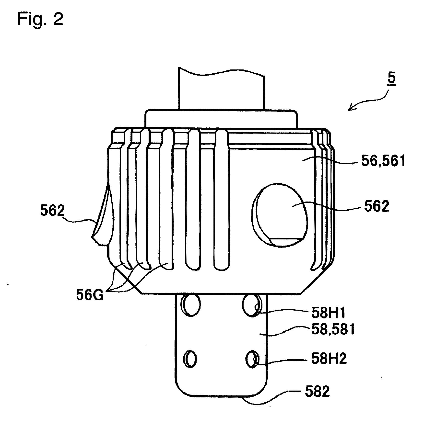
[0090]In the description of a liquid-condition detection sensor 1 according to the present embodiment as well as components thereof, the upper side along the direction of an axis O (axial direction) in FIG. 1 is called the proximal-end side, and the lower side is called the distal-end side.

[0091]The liquid-condition detection sensor 1 according to the present embodiment is used to detect, for example, the concentration and liquid level of a urea aqueous solution contained in a tank of an exhaust gas purification apparatus. The exhaust gas purification apparatus is used to render harmless nitrogen oxides (NOx) contained in exhaust gas from an automobile equipped with a diesel engine or the like by reducing the nitrogen oxides with the urea aqueous solution.

[0092]...


PUM

PropertyMeasurementUnit
electrically conductiveaaaaaaaaaa
elasticaaaaaaaaaa
diameteraaaaaaaaaa

Abstract

A liquid-condition detection sensor (1) including a sensor element (51), at least a portion of which contacts a urea aqueous solution; connection terminals (52) fixedly attached to the sensor element (51); connection cables (53) which electrically communicate with the concentration sensor element (51) via the connection terminals (52); an inner tube (42) which holds the concentration sensor element (51) at a distal end portion (421) by use of a holder member (55) and surrounds a portion of the connection cables (53) and the entire connection terminals (52); and a separator formed from a material having rubberlike elasticity (54) including a terminal-inner-tube-insulating portion (542) which intervenes between the connection terminals (52) and the inner tube (42) to thereby insulate the connection terminals (52) and the inner rube (42) from one another.

Description

FIELD OF THE INVENTION[0001]The present invention relates to a liquid-condition detection sensor for detecting the condition of a liquid to be measured.BACKGROUND OF THE INVENTION[0002]Exhaust gas emitted from automobiles equipped with a diesel engine or the like contains substances such as nitrogen oxides (NOx). In recent years, various measures haven been taken to purify such exhaust gas in order to protect as well as to prevent contamination of the environment. One measure used to purify exhaust gas is an exhaust gas purification apparatus.[0003]Such exhaust gas purification apparatus is mounted in an automobile and decomposes nitrogen oxides (NOx) to render them harmless by means of an NOx selective catalytic reduction (SCR) system. The NOx selective catalytic reduction (SCR) system employs a urea aqueous solution as a reducing agent. The urea aqueous solution is contained in a tank mounted in the automobile. In order to effectively decompose nitrogen oxides (NOx), the concentra...

Claims


Application Information

Patent Timeline
Patent Type & Authority Applications(United States)
IPC IPC(8): G01N33/00
CPCF01N3/206G01N25/005G01F23/268F01N2610/02
Inventor YAMAMOTO, TAKASHISASANUMA, TAKEOSATO, YOSHIKUNI
Owner NGK SPARK PLUG CO LTD
Why Eureka
Try Eureka