Steer-by-wire-system

Inactive Publication Date: 2007-07-26
JTEKT CORP
View PDF4 Cites 13 Cited by
  • Summary
  • Abstract
  • Description
  • Claims
  • Application Information

AI Technical Summary

Benefits of technology

[0010] Accordingly, in view of the foregoing circumstance, it is a primary object of the present invention to provide an improved steer-by-wire system capable of improving the returning of a steering handle while securing a ste

Problems solved by technology

This friction acts as a resistance against the returning of the steering handle to the neutral position in the steering system for the conventional vehicles and makes a cause to deteriorate the returning of the steering handle.
In the prior steer-by-wire system 1 as exemplified in the Patent Document 1, on the other hand, the phenomenon which is caused by such friction to deteriorate the returning of the steering handle does not arise, but another problem arises in that the state of the ro

Method used


Image

  • Steer-by-wire-system
  • Steer-by-wire-system
  • Steer-by-wire-system

Examples


first embodiment

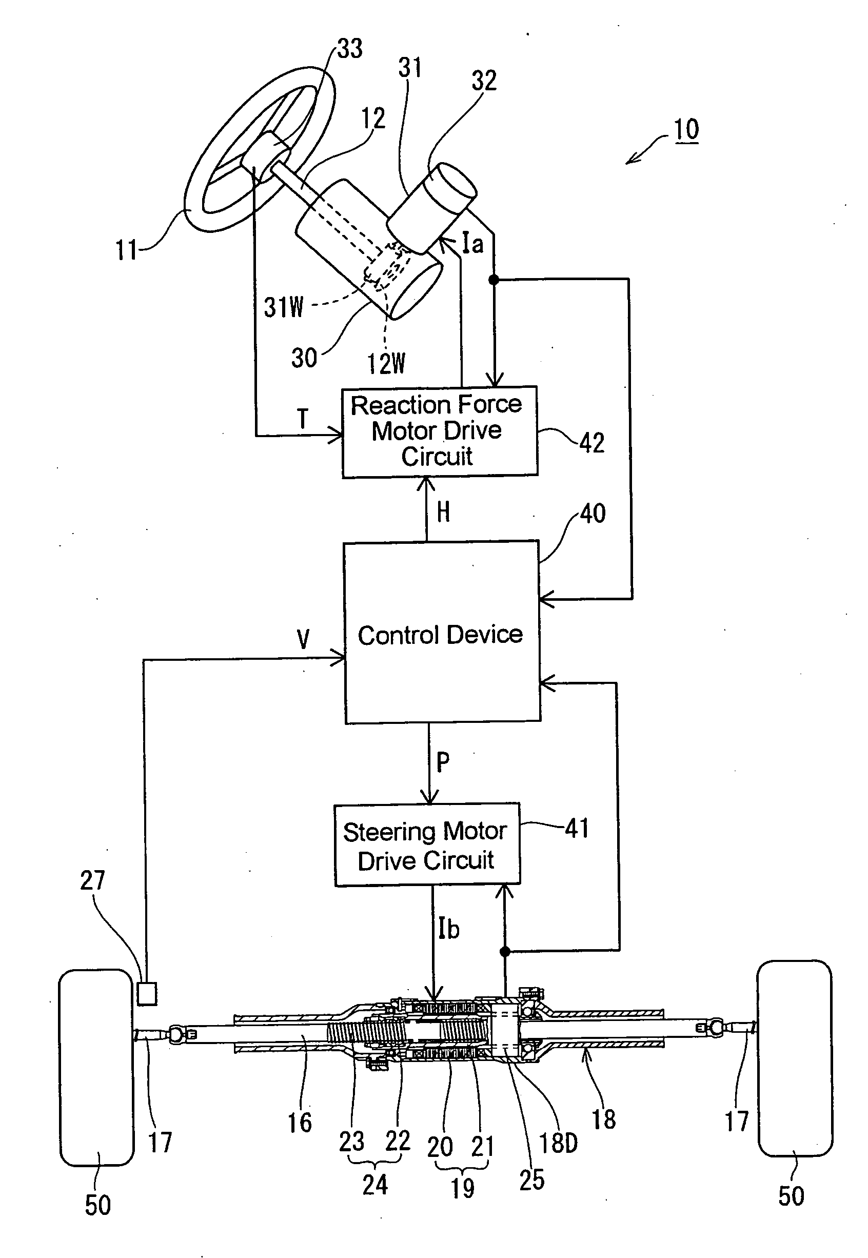
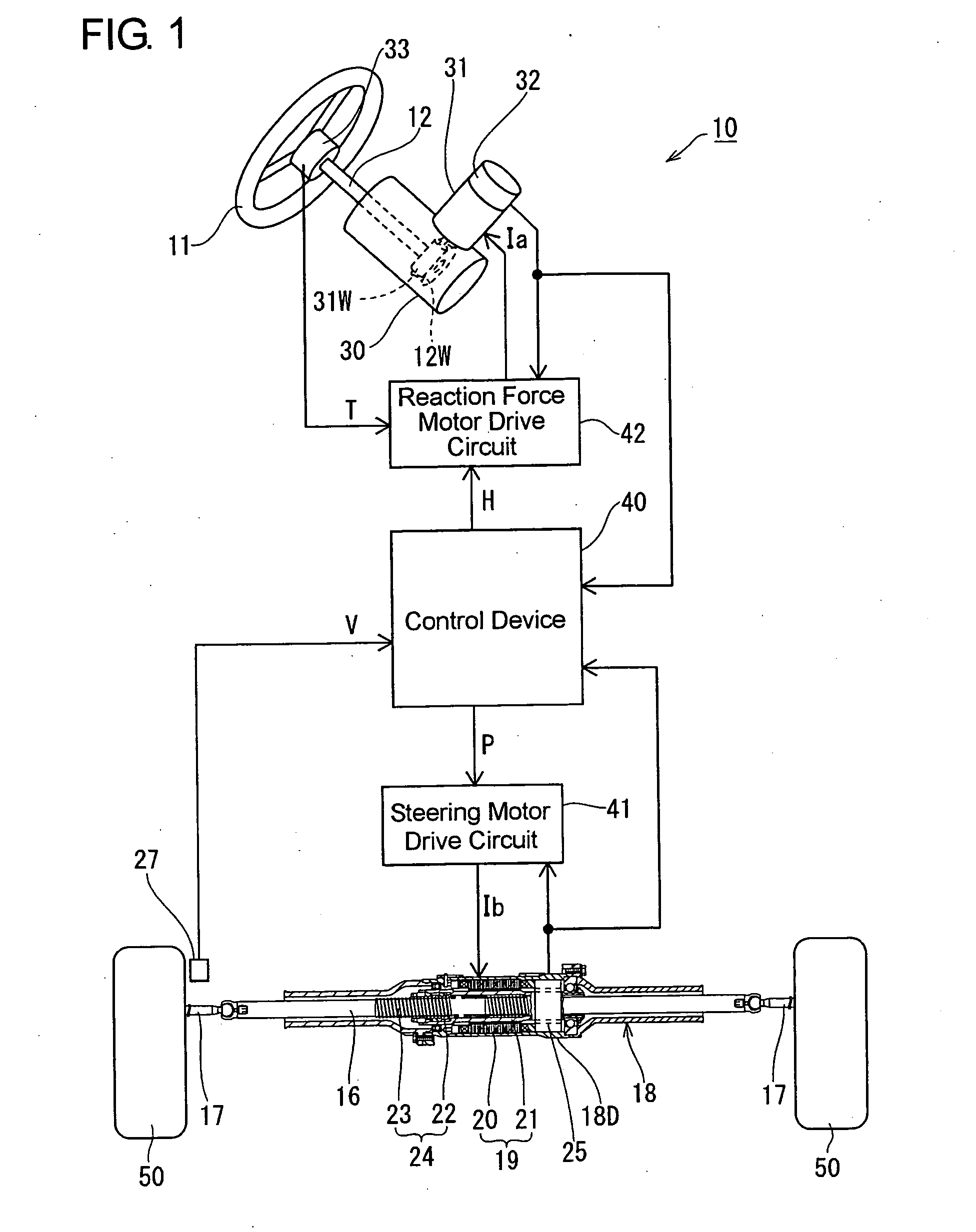
[0032] A first embodiment according to the present invention will be described hereafter with reference to FIGS. 1 to 11. FIG. 1 shows the entire construction of a steer-by-wire system 10 in the embodiment according to the present invention. In this steer-by-wire system 10, a steering handle 11 is mechanically disconnected from steerable wheels 50, 50. First of all, description will be made regarding components on the side of the steerable wheels 50, 50. An inter-steerable wheel shaft 16 is interposed between the pair of steerable wheels 50, 50, and tie rods 17 and 17 coupled to the opposite ends of the inter-steerable wheel shaft 16 are coupled respectively to the steerable wheels 50, 50.

[0033] The inter-steerable wheel shaft 16 passes through a cylindrical housing 18, which is secured to a body of a vehicle. A large-diameter section 18D is provided at an axially intermediate portion of the cylindrical housing 18, and a steering motor 19 is incorporated in the large-diameter secti...

second embodiment

[0051] FIGS. 12 to 17 show the second embodiment, which differs from the foregoing first embodiment in the constructions of a second made-up value determination processing (step S200) and a command value generation processing (step S300). Hereinafter, description will be made only regarding the constructions different from those in the first embodiment.

[0052] As shown in FIG. 12, when the second made-up value determination processing (step S200) in the second embodiment is executed, a first coefficient (Kv) is determined from the vehicle speed (V) by reference to a first coefficient determination map MP4 (refer to FIG. 13). Then, a second coefficient (Dv) is determined from the vehicle speed (V) by reference to a second coefficient determination map MP5 (refer to FIG. 14).

[0053] The first coefficient determination map MP4 is set so that the first coefficient (Kv) increases as the vehicle speed (V) increases, as shown in FIG. 13. Likewise, the second coefficient determination map M...


PUM


Abstract

In a steer-by-wire system 10, a first steering reaction force made-up value (Hc1) is determined in dependence on a road reaction force (W), and a second steering reaction force made-up value (Hc2) is determined in dependence on a steering position (X) of a steering handle 11 or steerable wheels 50. A steering reaction force command value (H) is generated from both of the first steering reaction force made-up value (Hc1) and the second steering reaction force made-up value (Hc2) the weightings on which are adjusted by respective weighting gains (G1, G2), and the ratio of the weighting gains is properly altered in dependence on the state of a road surface. Thus, it can be realized to provide the steer-by-wire system 10 capable of adjusting the steering reaction force to be sensitive or insensitive to the state of the road surface.

Description

INCORPORATION BY REFERENCE [0001] This application is based on and claims priority under 35 U.S.C. 119 with respect to Japanese Application No. 2004-318841 filed on Nov. 2, 2004, the entire content of which is incorporated herein by reference. BACKGROUND OF THE INVENTION [0002] 1. Field of the Invention [0003] The present invention relates to a steer-by-wire system wherein a steering handle of a vehicle is mechanically disconnected from a pair of steerable wheels and wherein a steering motor steers the steerable wheels in dependence on the manipulation of the steering handle while a reaction force motor generates a steering reaction force against the manipulation of the steering handle. [0004] 2. Discussion of the Related Art [0005] In conventional vehicles, when a steering handle is turned to steer steerable wheels from a neutral position (the position in which the steerable wheels are to be for traveling the vehicle straight ahead) during the traveling, a road reaction force (the ...

Claims


Application Information

Patent Timeline
IPC IPC(8): B62D5/00
CPCB62D6/008
Inventor OGAWA, SHOJISHIBATA, YOSHIYUKIKUROYANAGI, HIROSHIASAI, SHOJI
Owner JTEKT CORP
Why Eureka
Try Eureka