Acoustic resonator with impingement cooling tubes

Active Publication Date: 2007-07-26
SIEMENS ENERGY INC
View PDF25 Cites 90 Cited by
  • Summary
  • Abstract
  • Description
  • Claims
  • Application Information

AI Technical Summary

Benefits of technology

[0008] The first end of each cooling tube is operatively connected to the resonator plate such that the inner passage of each cooling tube is in fluid communication with a respective passage in the resonator plate. The length of each cooling tube is less than the length of the side wall. In one embodiment, each of the cooling tubes can have substantially the same length.
[0009] The cooling tubes ca

Problems solved by technology

Resonators can dampen undesired frequencies of dynamics that may develop in the engine during operation.
However, one tradeoff to these larger resonators is that the cooling holes becomes less effective in cooling the surface below, especially when resonator height is increased.
As a result, the impingement cooling holes become less effective in cooling the hot surface.
Thus, there can be concerns of overheating of the component and/or the

Method used


Image

  • Acoustic resonator with impingement cooling tubes
  • Acoustic resonator with impingement cooling tubes
  • Acoustic resonator with impingement cooling tubes

Examples


Embodiment Construction

[0025] Embodiments of the invention are directed to resonators adapted to increase their cooling effectiveness. Aspects of the invention will be explained in connection with various resonator configurations, but the detailed description is intended only as exemplary. Embodiments of the invention are shown in FIGS. 1-5, but the present invention is not limited to the illustrated structure or application.

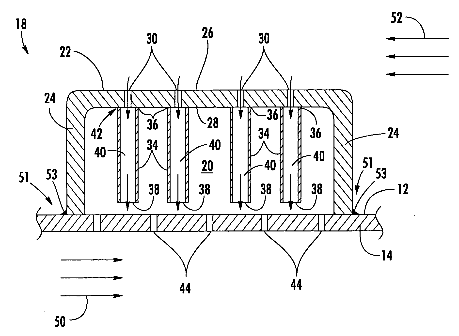
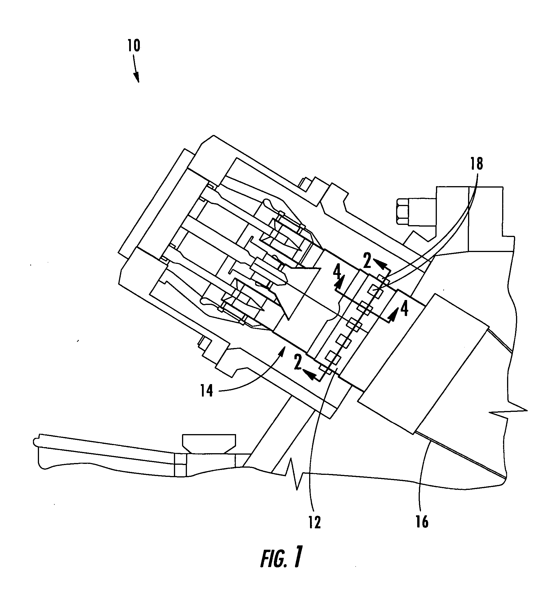
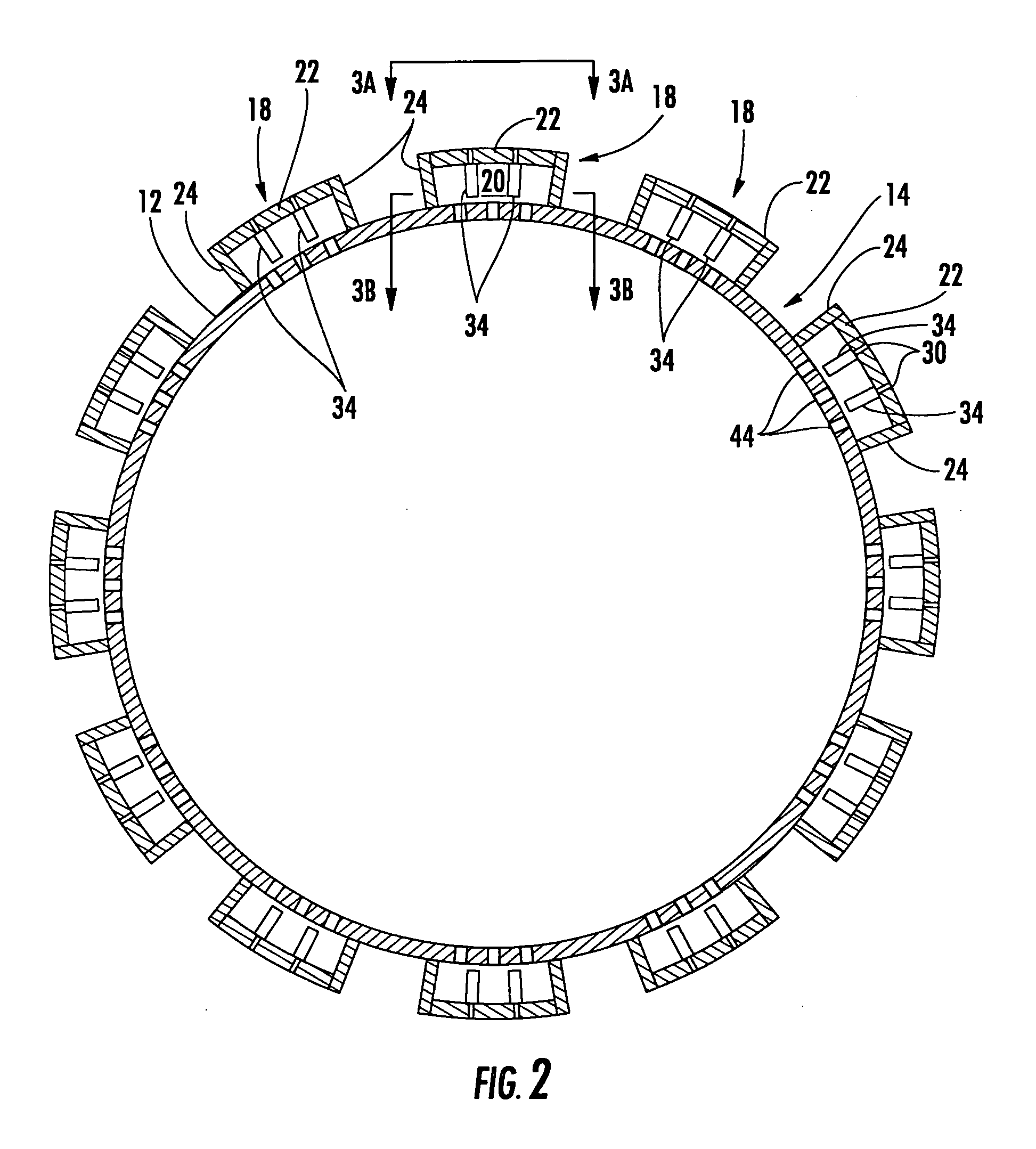
[0026]FIG. 1 shows an example of a portion of the combustor section 10 of a turbine engine. It should be noted that aspects of the invention can be applied to various turbine engine combustor systems including annular, can and can-annular combustors, just to name a few possibilities. Aspects of the invention are not intended to be limited to any particular type of combustor, turbine engine or application. As shown, one or more damping devices can be operatively connected to a surface 12 of a combustor component, such as a liner 14 or a transition duct 16. One commonly used damping de...


PUM


Abstract

Aspects of the invention are directed to an acoustic resonator with improved impingement cooling effectiveness. The resonator includes a plate with an inside face and an outside face. A plurality of passages extend through the plate. The resonator includes a side wall that extends from and about the plate. A plurality of cooling tubes are attached to the resonator plate such that an inner passage of each cooling tube is in fluid communication with a respective passage in the resonator plate. The resonator can be secured to a surface of a turbine engine combustor component to define a closed cavity. The ends of the cooling tubes are spaced from the surface. Thus, a coolant can enter the passages in the plate and can be directed to the surface so as to impingement cool the surface. The cooling tubes can minimize coolant loss by dispersion in the cavity.

Description

FIELD OF THE INVENTION [0001] The invention relates in general to devices for suppressing acoustic energy and, more particularly, to the use of such devices in power generation applications. BACKGROUND OF THE INVENTION [0002] The use of damping devices, such as Helmholtz resonators, in turbine engines is known. For instance, various examples of resonators are disclosed in U.S. Pat. No. 6,530,221, which is incorporated herein by reference. Resonators can dampen undesired frequencies of dynamics that may develop in the engine during operation. [0003] One or more resonators can be attached to a surface of a turbine engine component, such as a combustor liner. The resonators are commonly attached to the component by welding. Some resonators can include a plurality of passages through which air can enter and purge the cavity enclosed by the resonator. One beneficial byproduct of such airflow is that the component to which the resonator is attached can be impingement cooled. That is, cool...

Claims


Application Information

Patent Timeline
IPC IPC(8): E04B1/82
CPCF23M20/005F23R2900/00014
Inventor WASIF, SAMERJOHNSON, CLIFFORD
Owner SIEMENS ENERGY INC
Why Eureka
Try Eureka