Disc brake pad, back plate for pad and method of manufacturing back plate for pad

a disc brake and back plate technology, applied in the direction of brake types, braking elements, braking members, etc., can solve the problems of disc brakes increasing in size, increasing material weight, increasing material cost, etc., and achieves the effect of increasing the adhesion area between the friction material and the back plate, enhancing adhesion strength, and keeping the adhesion strength high

a disc brake and back plate technology, applied in the direction of brake types, braking elements, braking members, etc., can solve the problems of disc brakes increasing in size, increasing material weight, increasing material cost, etc., and achieves the effect of increasing the adhesion area between the friction material and the back plate, enhancing adhesion strength, and keeping the adhesion strength high

US20070170023A1Inactive Publication Date: 2007-07-26YAMAMOTO CORPORATION

Image

  • Disc brake pad, back plate for pad and method of manufacturing back plate for pad
  • Disc brake pad, back plate for pad and method of manufacturing back plate for pad
  • Disc brake pad, back plate for pad and method of manufacturing back plate for pad

Examples


Embodiment Construction

[0044] Preferred embodiments according to the present invention will be described hereunder with reference to the accompanying drawings.

[0045] First, a back plate for a disc brake pad (hereinafter referred to as ā€œback plateā€) according to an embodiment of the present invention will be described hereunder with the accompanying drawings.

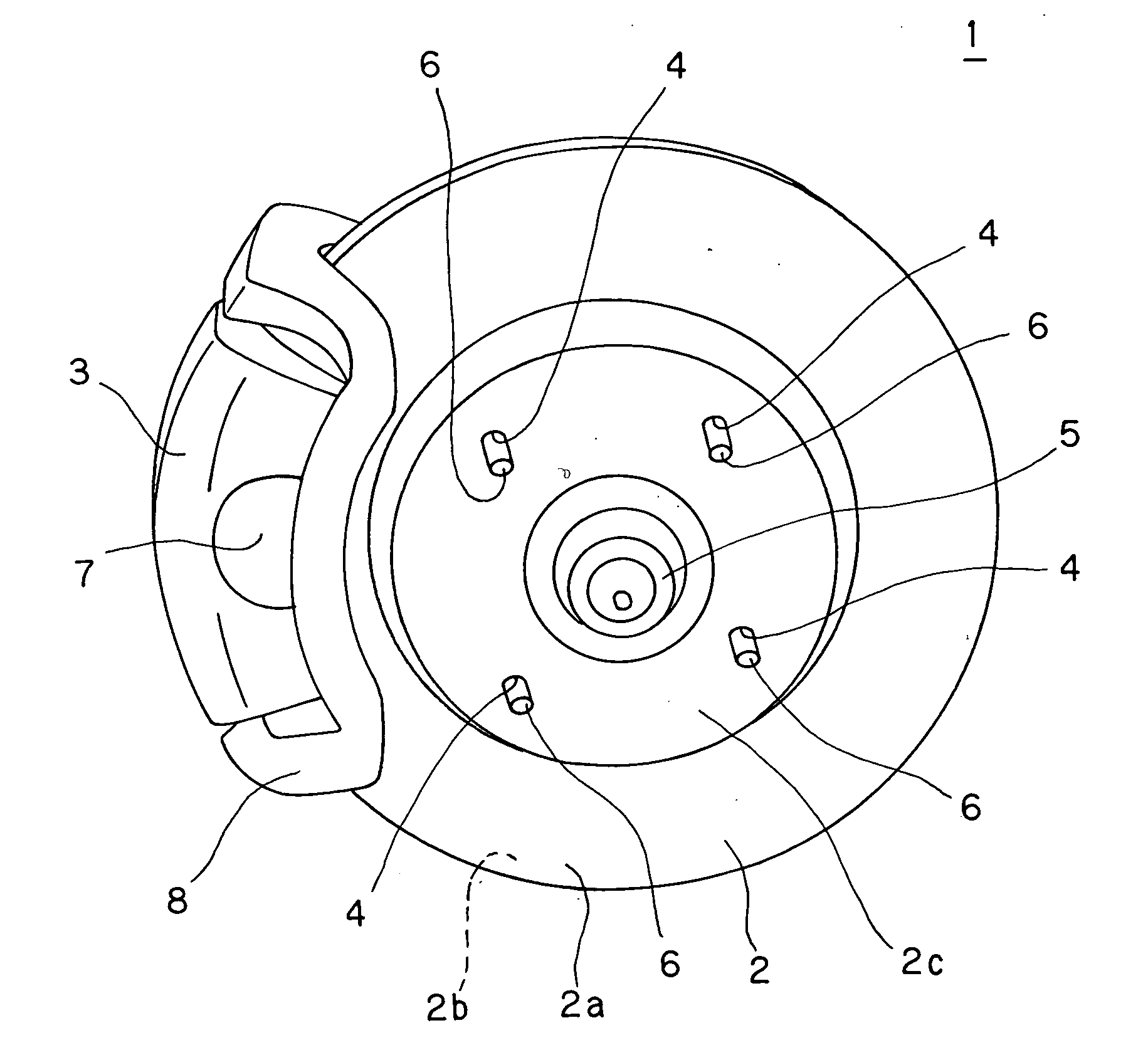
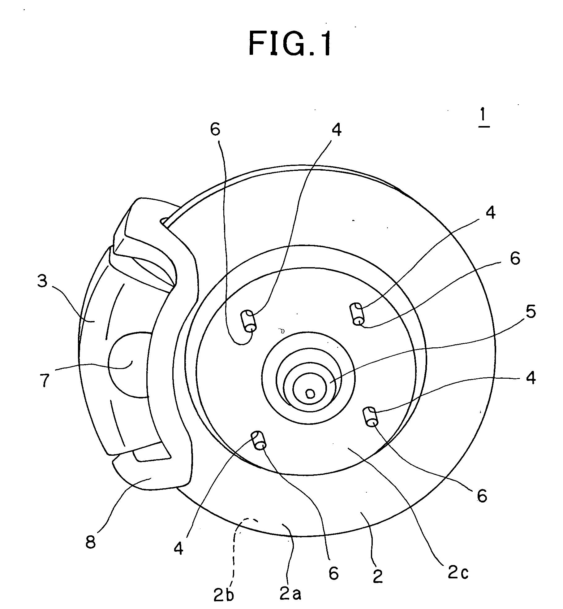
[0046]FIG. 1 is a diagram showing a disc brake using the back plate according to the embodiment of the present invention.

[0047] A disc brake 1 used for a vehicle or the like is equipped with a brake disc 2 rotatable together with an axle 5, and a caliper 3 disposed at the peripheral edge portion of the brake disc 2.

[0048] As shown in FIG. 1, the brake disc 2 is designed in a disc-like shape having a hub 2c at the center portion thereof, and also two flat face portions 2a and 2b along which friction materials described later frictionally slide are provided to the outer peripheral edge portion of the disc plate. Furthermore, the hub 2c at the center ...


PUM


Abstract

A back plate for a disc brake pad including a friction material fixing face provided to one surface of the back plate so that a friction material is fixed to the friction material fixing face, and plural projections provided to the friction material fixing face so as to project to the friction material side. The projections are formed by pressing (for example, stamping) the back plate from the other surface thereof at the opposite side to the friction material fixing face in a progressive working based on fine blanking press so that the projections concerned are extruded from the friction material fixing face.

Description

BACKGROUND OF THE INVENTION [0001] 1. Field of the Invention [0002] The present invention relates to a disc brake pad mounted in a disc brake used for braking of a vehicle, a railcar, an industrial machine or the like, a back plate for a disc brake pad (hereinafter referred to as ā€œbackplateā€) used for supporting a friction material of the disc brake pad, and also a method of manufacturing the back plate. [0003] 2. Description of the Related Art [0004] A general type disc brake used for vehicles, etc. is equipped with a disc-shaped brake disc that is secured to a rotating axle side and rotates together with the axle, and a caliper that is secured to the main body side of the vehicle and pinches the peripheral edge portion of the brake disc from both the side surfaces thereof. The caliper is equipped with a pair of disc brake pads, and these disc brake pads are disposed so as to be spaced from each other at a predetermined interval and confront each other through the brake disc. Each ...

Claims


Application Information

Patent Timeline
26 Jul 2007
Publication
US20070170023A1
IPC
F16D65/00
CPC
F16D65/092; F16D2069/0491; F16D2069/0441; F16D69/04; B21D22/02; B23P15/18
Inventors
YAMAMOTO, KATSUHIRO