Color LED driver

a technology of led drivers and led light, applied in static indicating devices, instruments, optics, etc., can solve the problem that the temperature compensation circuit is hardly used in the backlight of the mobile device, and achieve the effect of low cost and small siz

Active Publication Date: 2007-07-26
SAMSUNG ELECTRONICS CO LTD
View PDF8 Cites 82 Cited by
  • Summary
  • Abstract
  • Description
  • Claims
  • Application Information

AI Technical Summary

Benefits of technology

[0016]The present invention has been made to solve the foregoing problems of the prior art and therefore an aspect of the present invention is to provide a color LED driver, which is capable of being implemented by a compact structure without a feedback structure and accompanying a small size and low cost, by directly connecting a negative temperature coefficient (NTC) thermistor to a driving current path of a color LED applied to a LCD backlight to compensate a characteristic variation of the LED due to a variation in a temperature.

Problems solved by technology

As a result, a temperature compensation circuit is hardly used in the backlight for the mobile device.

Method used


Image

  • Color LED driver
  • Color LED driver
  • Color LED driver

Examples


Embodiment Construction

[0032]Preferred embodiments of the present invention will now be described in detail with reference to the accompanying drawings.

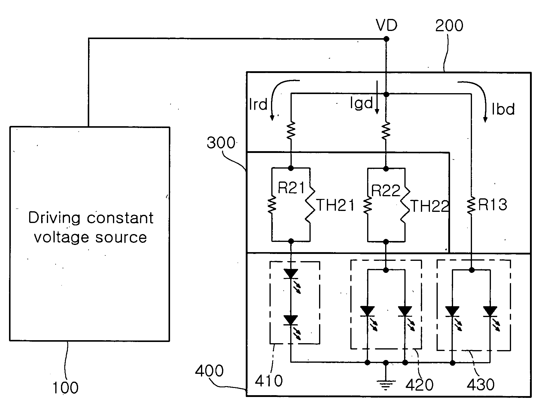
[0033]FIG. 3 is a view showing the configuration of a color LED driver according to the present invention.

[0034]Referring to FIG. 3, the color LED driver according to the present invention includes a driving constant voltage source 100, a driving circuit 200, a temperature compensation unit 300 and an LED unit 400.

[0035]The driving constant voltage source 100 supplies a predetermined driving constant voltage VD to the driving circuit 200. Since the driving constant voltage VD is always a uniform voltage (e.g., 5V) regardless of load resistance, driving current can be adjusted by varying a resistor.

[0036]The driving circuit 200 converts the driving constant voltage VD of the driving constant voltage source 100 into a plurality of driving currents, for driving the color LEDs. Here, the plurality of driving currents includes red LED driving current Ird, green...


PUM


Abstract

Disclosed herein is a color LED driver, which is capable of being implemented by a compact structure without a feedback structure and accompanying a small size and low cost, by directly connecting a negative temperature coefficient (NTC) thermistor to a driving current path of a color LED applied to an LCD backlight to compensate a characteristic variation of the LED due to a variation in a temperature. The color LED driver includes a driving constant voltage source 100 which supplies a predetermined driving constant voltage VD; a driving circuit 200 which converts the driving constant voltage VD of the driving constant voltage source 100 into a plurality of driving currents, for driving color LEDs, the plurality of driving currents including red LED driving current Ird, green LED driving current Igd and blue LED driving current Ibd; a temperature compensation unit 300 which compensates variations in the red LED driving current Ird and the green LED driving current Igd due to a variation in a temperature, among the plurality of driving currents from the driving circuit 200; and an LED unit 400 including a plurality of color LEDs which are turned on by the driving currents from the temperature compensation circuit 300 and the driving current from the driving circuit 200.

Description

CLAIM OF PRIORITY[0001]This application claims the benefit of Korean Patent Application No. 2006-7459 filed on Jan. 24, 2006, in the Korean Intellectual Property Office, the disclosure of which is incorporated herein by reference.BACKGROUND OF THE INVENTION[0002]1. Field of the Invention[0003]The present invention relates to a color light-emitting diode (LED) driver of an LCD backlight, and more particularly, to a color LED driver, which is capable of being implemented by a compact structure without a feedback structure and accompanying a small size and low cost, by directly connecting a negative temperature coefficient (NTC) thermistor to a driving current path of a color LED applied to an LCD backlight to compensate a characteristic variation of the LED due to a variation in a temperature.[0004]2. Description of the Related Art[0005]Generally, a white LED has been widely used in a mobile device as a light source of a LCD backlight. In a middle-sized or large-sized LCD backlight, a...

Claims


Application Information

Patent Timeline
Patent Type & Authority Applications(United States)
IPC IPC(8): G09G3/32H01L33/00H05B37/02H05B44/00
CPCG09G3/3413H05B33/0857H05B33/0809H05B45/37H05B45/28G09G3/20G09G3/32G02F1/133G09G3/36
Inventor LEE, DONG WOO
Owner SAMSUNG ELECTRONICS CO LTD
Why Eureka
Try Eureka