
Image static area determination apparatus and interlace progressive image transform apparatus

a technology of image static area determination and progressive image transformation, which is applied in the direction of signal generators with optical-mechanical scanning, selective content distribution, television systems, etc., can solve the problems of flicker in frame images in the progressive scanning system, and the inability to detect motion between frame images

Inactive Publication Date: 2007-07-26
FUJITSU MICROELECTRONICS LTD
View PDF5 Cites 15 Cited by
  • Summary
  • Abstract
  • Description
  • Claims
  • Application Information

AI Technical Summary

Benefits of technology

"The present invention aims to solve problems related to image processing such as flicker and blur. It proposes a method for determining a static area between consecutive frame images by comparing not only two consecutive frame images, but also a pseudo-field image generated by interpolation from a later field image. This allows for detecting motion that cannot be detected between frames, such as the motion of stripes. By applying this static area determination system to an interlace-progressive image transform, a frame image corresponding to a result of correctly detecting a motion can be generated."

Problems solved by technology

For example, there is the problem that flicker occurs in a frame image in the progressive scanning system transformed from a field image in the interlace scanning system.
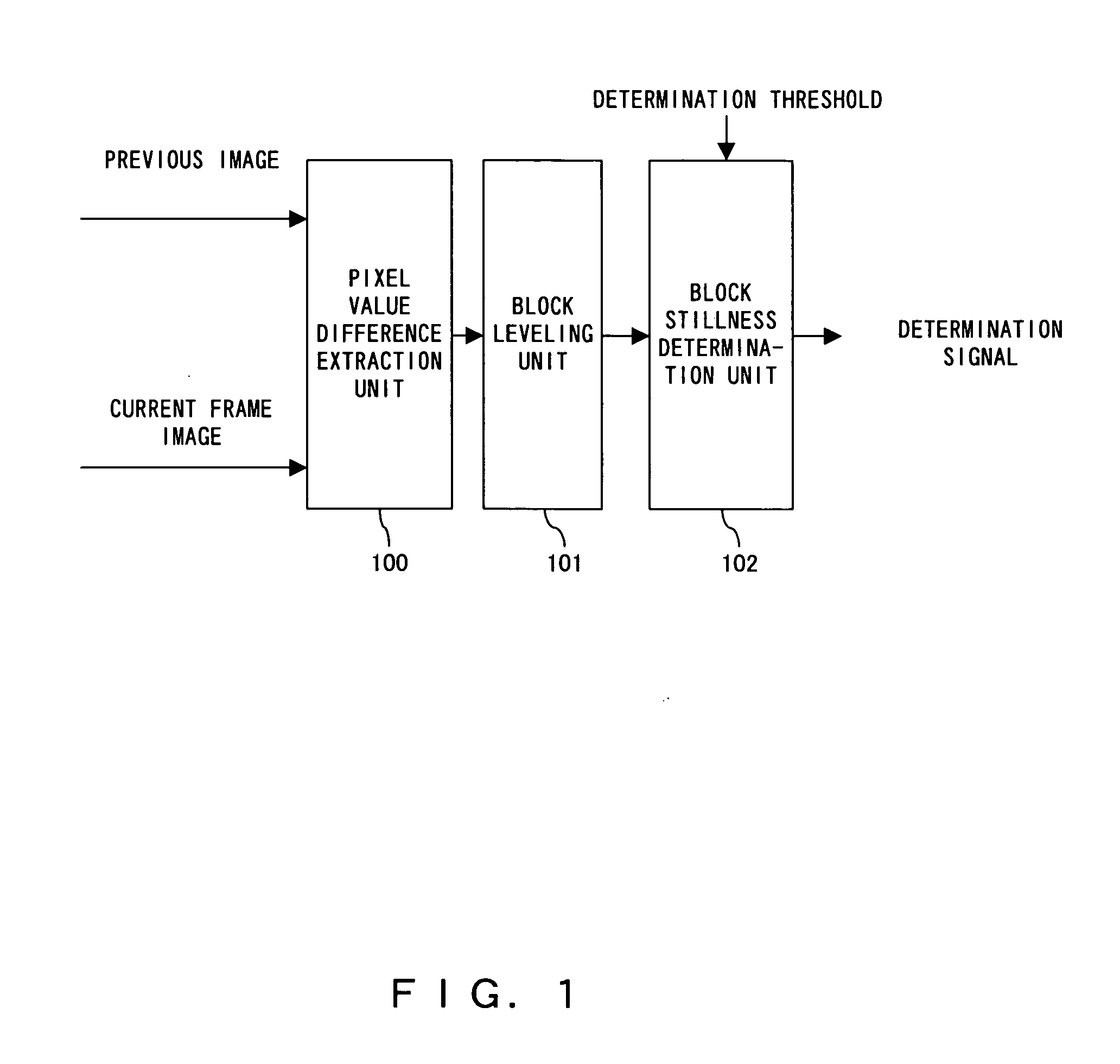
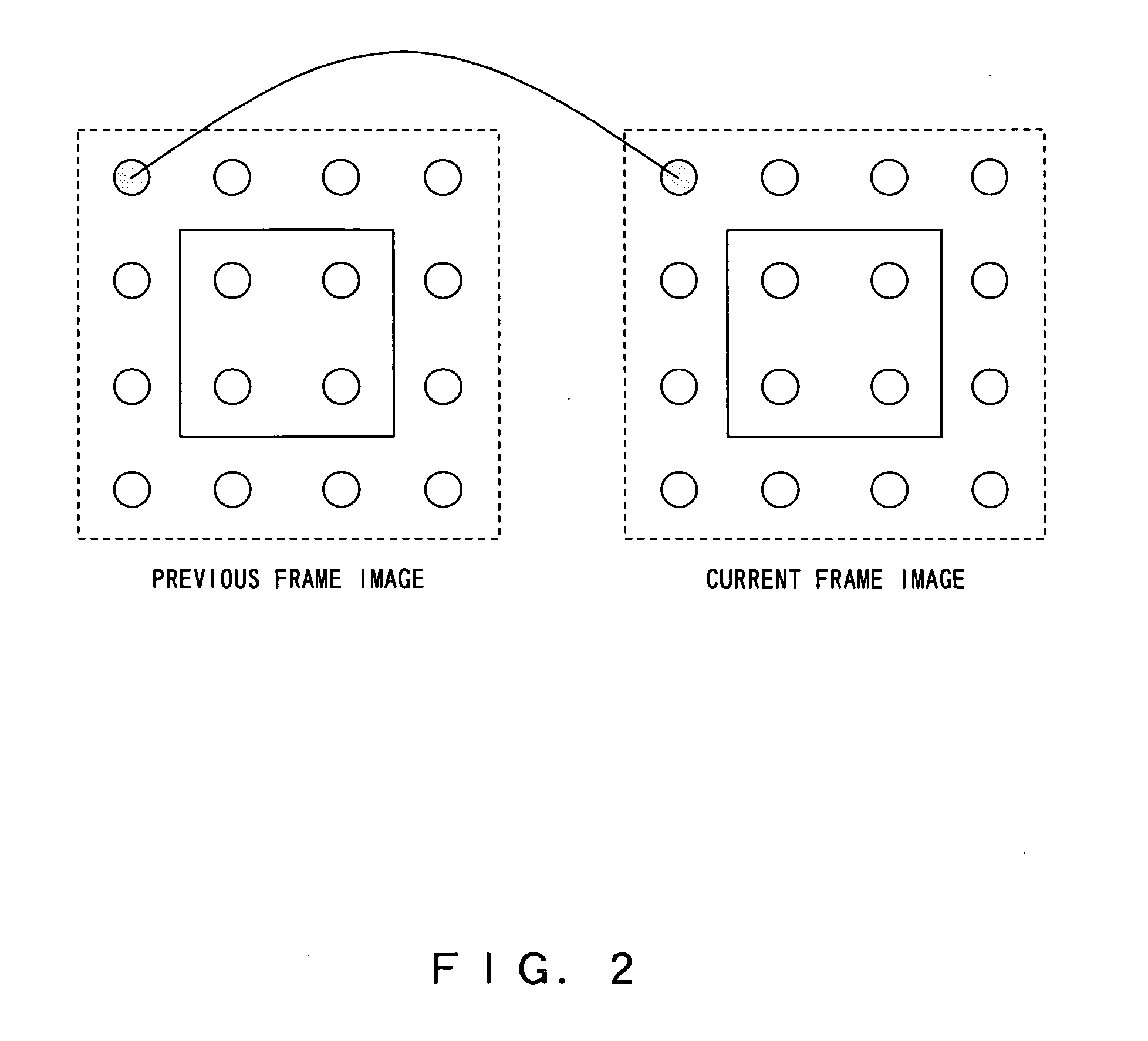
However, in the technology of the patent document 1, since the difference in pixel value is obtained only between the pixels in consecutive frames, the difference in pixel value caused by a slight motion of an image has an influence on determining a static area, a result of the image signal processing causes flicker and a blur.
As described above, contrary to the problem that a very small motion not detected by naked eyes can be determined that a block to be determined is not a static area when a determination on a static area is made only by a difference in pixel value of the corresponding pixels between consecutive frame images, there is the problem that a motion to be detected that there is a motion between frame images cannot be detected.

Method used


Image

  • Image static area determination apparatus and interlace progressive image transform apparatus
  • Image static area determination apparatus and interlace progressive image transform apparatus
  • Image static area determination apparatus and interlace progressive image transform apparatus

Examples


Embodiment Construction

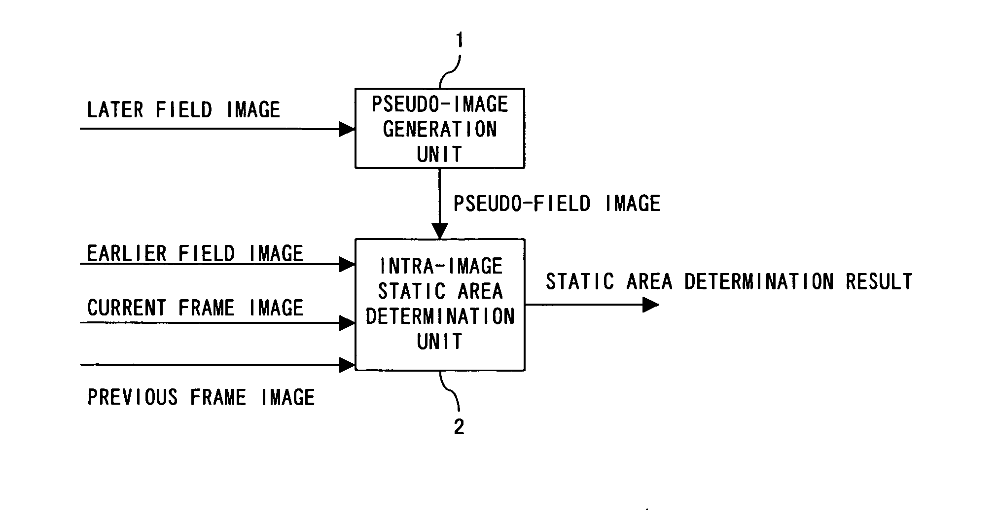
[0045]FIG. 8 is a block diagram of the configuration showing the principle of the image static area determination apparatus according to the present invention. In FIG. 8, the image static area determination apparatus includes a pseudo-image generation unit 1 and an intra-image static area determination unit 2.

[0046] The pseudo-image generation unit 1 obtains a pseudo-field image of an earlier field image by interpolation from a later field image in the two consecutive frame images in the interlace scanning system, and the intra-image static area determination unit 2 determines a static area in an image upon receipt of the input of a current frame image, a previous frame image, an earlier field image, and a pseudo-field image.

[0047] In the embodiment of the present invention, the intra-image static area determination unit 2 can also comprise a static area determination unit for determining a static area in the images upon receipt of the input of the current frame image and the prev...


PUM


Abstract

A unit for generating a pseudo image of an earlier field image by interpolation from a later field image in two consecutive field images in an interlace scanning system, and a unit of determining a static area in the images upon receipt of the input of a current frame image, a previous frame image, an earlier field image, and a pseudo-field image are included. A motion which cannot be detected between frame images can be detected by comparing an earlier field image with apseudo-field image.

Description

CROSS REFERENCE TO RELATED APPLICATIONS [0001] This application is based upon and claims the benefit of priority from the prior Japanese Patent Application No. 2006-013074, filed on Jan. 20, 2006, the entire contents of which are incorporated herein by reference. BACKGROUND OF THE INVENTION [0002] 1 Field of the Invention [0003] The present invention relates to a system of processing, for example, a video image, and more specifically to, for example, an apparatus for determining a static area between consecutive frame images, and an image transform device for transforming a field image in an interlace scanning system to a frame image in a progressive scanning system by applying the determination apparatus. [0004] 2. Description of the Related Art [0005] For example, in a video signal processing device, determining a static area between consecutive frames is an important technique for efficient signal processing. For example, in transforming a field image in the interlace scanning sy...

Claims


Application Information

Patent Timeline
Patent Type & Authority Applications(United States)
IPC IPC(8): H04N7/01
CPCH04N5/144H04N7/012H04N21/2368H04N21/4341H04N21/44008H04N19/59H04N19/112H04N19/16H04N19/17H04N19/543H04N21/4402
Inventor TATSUMI, MASAHIRO
Owner FUJITSU MICROELECTRONICS LTD
Learn More