
Sequential wavefront sensor

Inactive Publication Date: 2007-07-26
CLARITY MEDICAL SYST
View PDF12 Cites 90 Cited by
  • Summary
  • Abstract
  • Description
  • Claims
  • Application Information

AI Technical Summary

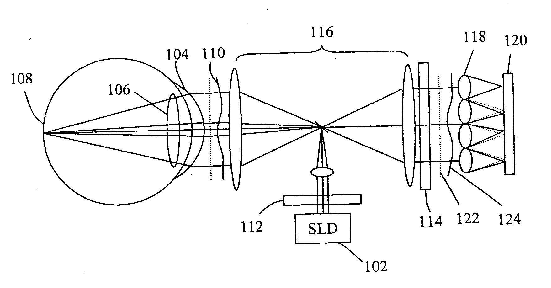
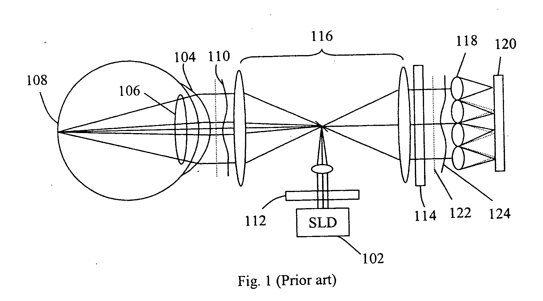
Problems solved by technology

In such a case, a large portion of the CCD detector arrays read out would be wasted.
However, with this arrangement, it is still necessary to use a multiple number of quad-detectors, which, although, are collectively less expensive than a large area CCD camera, but are still more costly than a single quad-detector.
In addition, alignment a number of quad-detectors will also be much more difficult than that of a single quad-detector.

Method used


Image

  • Sequential wavefront sensor
  • Sequential wavefront sensor
  • Sequential wavefront sensor

Examples


Embodiment Construction

[0017] Reference will now be made in detail to various embodiments of the invention. Examples of these embodiments are illustrated in the accompanying drawings. While the invention will be described in conjunction with these embodiments, it will be understood that it is not intended to limit the invention to any embodiment. On the contrary, it is intended to cover alternatives, modifications, and equivalents as may be included within the spirit and scope of the invention as defined by the appended claims. In the following description, numerous specific details are set forth in order to provide a thorough understanding of the various embodiments. However, the present invention may be practiced without some or all of these specific details. In other instances, well known process operations have not been described in detail in order not to unnecessarily obscure the present invention.

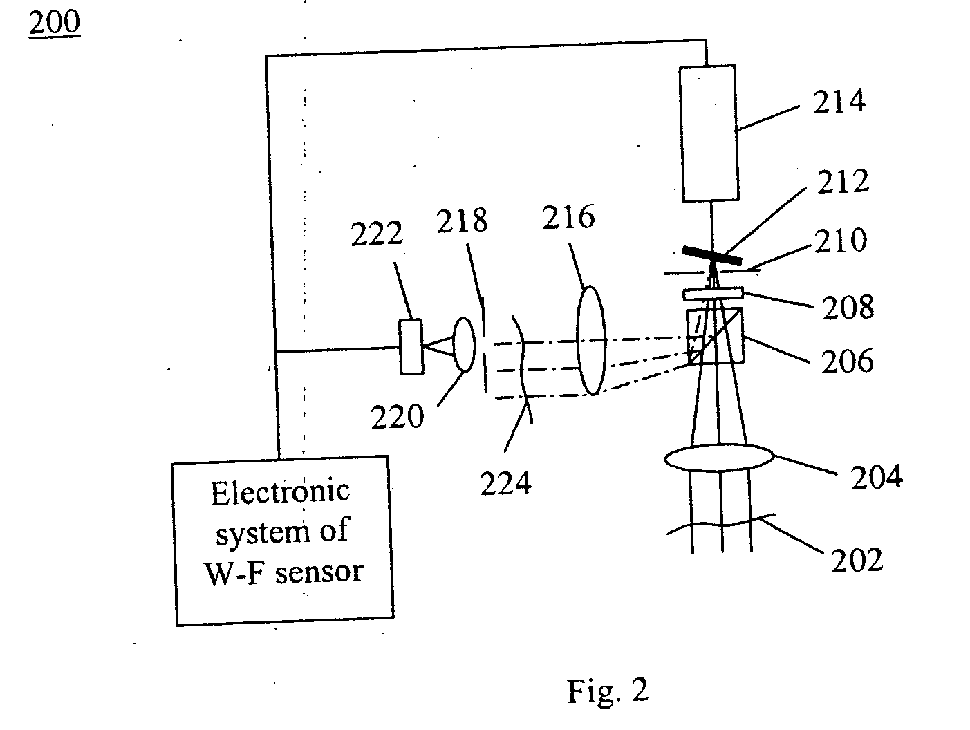
[0018] One embodiment of the present invention is a sequential wavefront sensor comprising a light beam...


PUM


Abstract

A sequential wavefront sensor comprises a light beam scanning module, a sub-wavefront focusing lens, a detector with more than one photosensitive area and a processor for calculating the sequentially obtained centroids of a number focused light spots from the sub-wavefronts to determine the aberration of the input wavefront. A sequential wavefront sensing method comprises the steps of; sequentially projecting a number of sub-wavefronts onto a sub-wavefront focusing lens and a detector with more than one photosensitive areas, calculating the centroid of the focused light spot from each sub-wavefront, and processing the centroid information to determine the aberration of the wavefront. In particular, a method for auto-focusing and / or auto-astigmatism-correction comprises the steps of sequentially projecting a number of sub-wavefronts around an annular ring of a wavefront to a sub-wavefront focusing lens and a detector, calculating the centroid of focused light spot from each sub-wavefront to figure out the centroid trace and hence the defocus and / or astigmatism, adjusting the focus and / or astigmatism of the optical imaging system before the wavefront sensor so that the measured defocus and / or astigmatism is minimized.

Description

BACKGROUND OF THE INVENTION [0001] Wavefront sensors are devices used to measure the shape of the wavefront of a light beam (see, for example, U.S. Pat. No. 4,141,652). In most cases, a wavefront sensor measures the departure of a wavefront from a reference wavefront or an ideal wavefront such as a plane wavefront. A wavefront sensor can be used for measuring both low order and high order aberrations of various optical imaging systems such as the human eye (see for example, J. Liang, et al. (1994) “Objective measurement of the wave aberrations of the human eye with the use of a Hartmann-Shack wave-front sensor,” J. Opt. Soc. Am. A 11, 1949-1957; T. Dave (2004) “Wavefront aberrometry Part 1: Current theories and concepts” Optometry Today, 2004 Nov. 19, page 41-45). Furthermore, a wavefront sensor can also be used in adaptive optics in which the distorted wavefront can be measured and compensated in real time, using, for example, an optical wavefront compensation device such as a defo...

Claims


Application Information

Patent Timeline
IPC IPC(8): A61B3/10
CPCG01J9/00A61B3/14G01J1/0414G01J1/0437A61B3/1015G01J3/06A61B3/12
Inventor SU, WEIZHOU, YANZHAO, QING CHUN
Owner CLARITY MEDICAL SYST
Learn More