Distortion measuring apparatus, method, program, and recording medium

a technology of optical fiber and measuring apparatus, applied in the direction of measuring devices, testing fibre optic/optical waveguide devices, instruments, etc., can solve the problems of degrading the precision of measuring optical fiber distortion, detecting peak frequency,

Inactive Publication Date: 2007-07-26
ADVANTEST CORP
View PDF1 Cites 13 Cited by
  • Summary
  • Abstract
  • Description
  • Claims
  • Application Information

AI Technical Summary

Benefits of technology

[0016] According to the present invention, the distortion measuring device may include: a continuous wave light source that generates continuous wave light; an optical pulse generator that converts the continuous wave light into pulsed light; an optical frequency shifter that receives the continuous wave light, and outputs shifted light including the continuous wave light, first side band light having an optical frequency higher than an optical frequency of the continuous wave light by a predetermined optical frequency, and second side band light having an optical frequency lower than the optical frequency of the continuous wave light by the predetermined optical frequency; a heterodyne optical receiver that receives scattered light from an incident end of the device under test which the pulsed light enters, further receives the shifted light from the optical frequency shifter, and outputs an electric signal having a frequency which is a difference between the optical frequency of the scattered light and the optical frequency of the shifted light; a Brillouin scattered light spectrum extracting unit that extracts an electric signal corresponding to the Brillouin scattered light from the electric signal; and a Rayleigh scattered light spectrum extracting unit that extracts an electric signal corresponding to the Rayleigh scattered light from the electric signal.

Problems solved by technology

As a result, precision to detect the peak frequency degrades, and further, precision to measure the distortion of the optical fiber degrades.

Method used


Image

  • Distortion measuring apparatus, method, program, and recording medium
  • Distortion measuring apparatus, method, program, and recording medium
  • Distortion measuring apparatus, method, program, and recording medium

Examples


Embodiment Construction

[0028] A description will now be given of an embodiment of the present invention with reference to drawings.

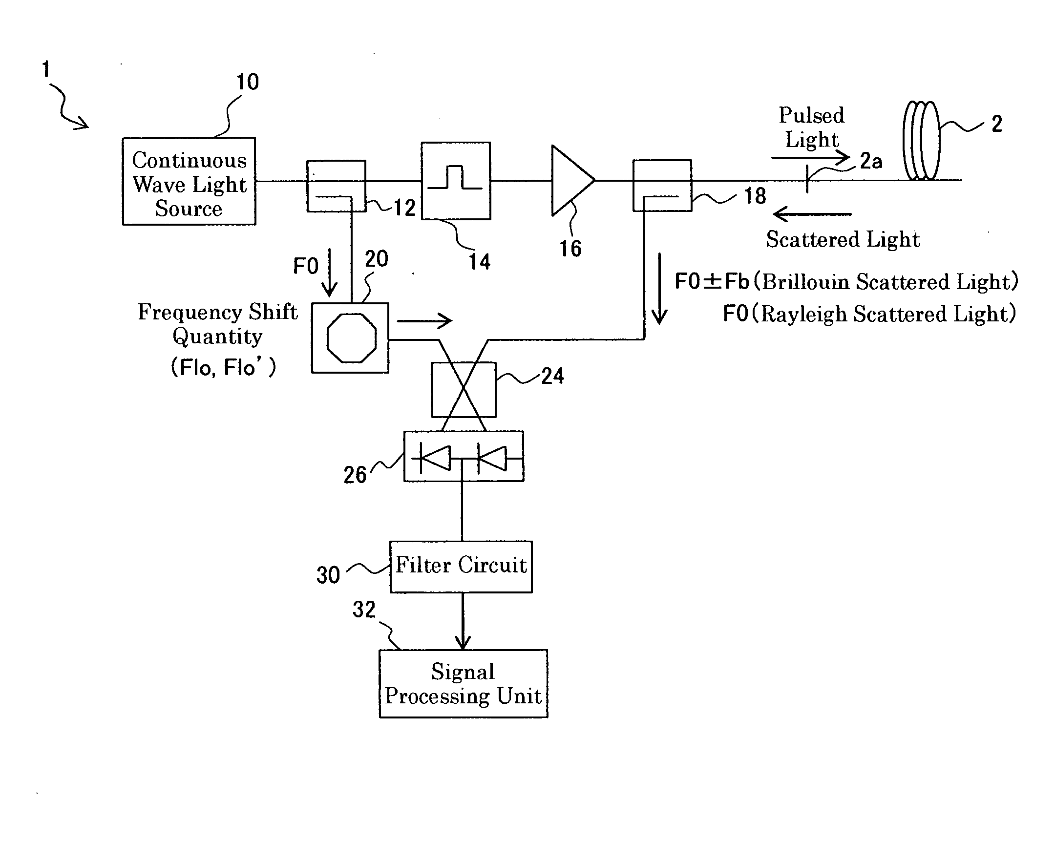
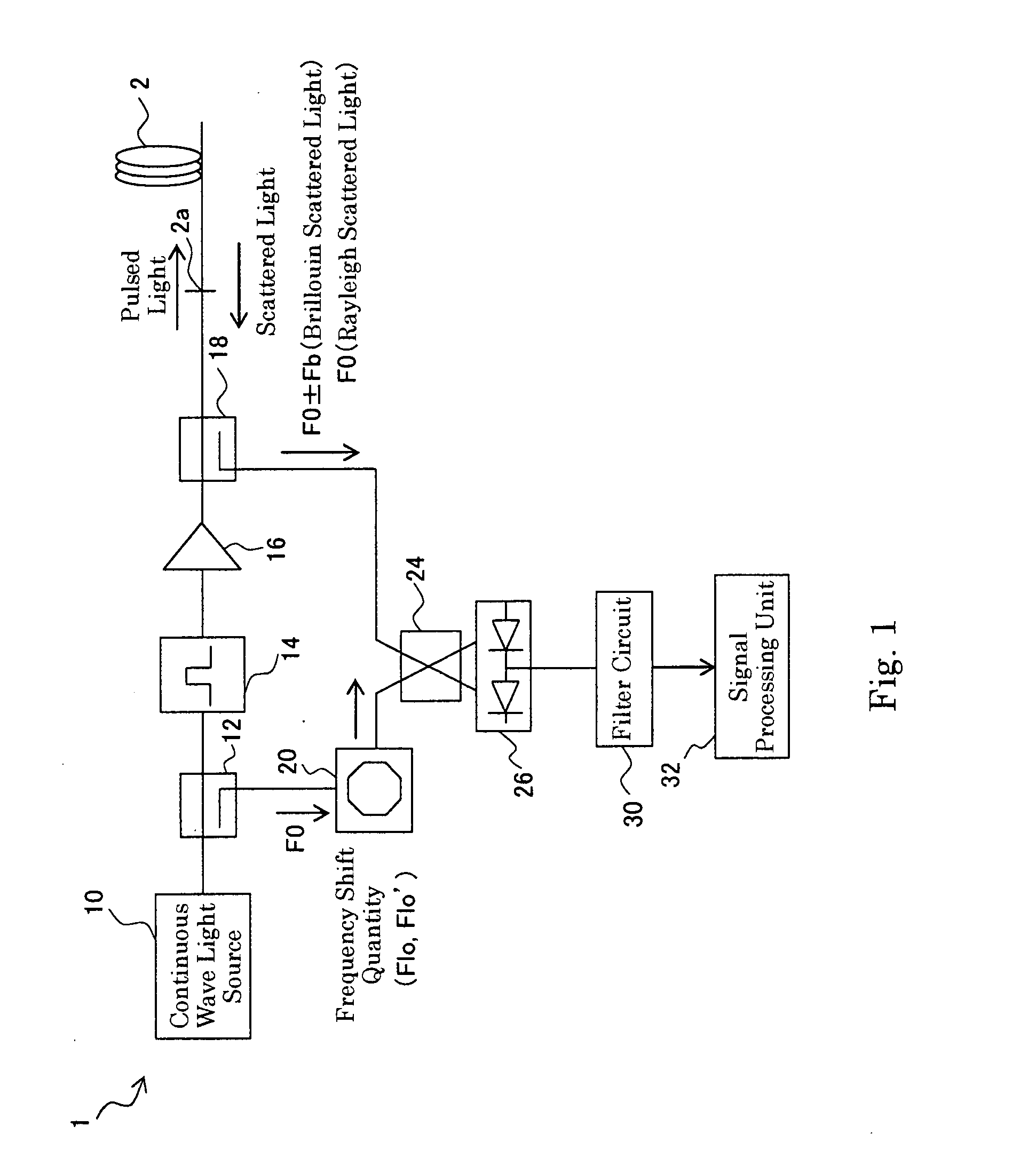
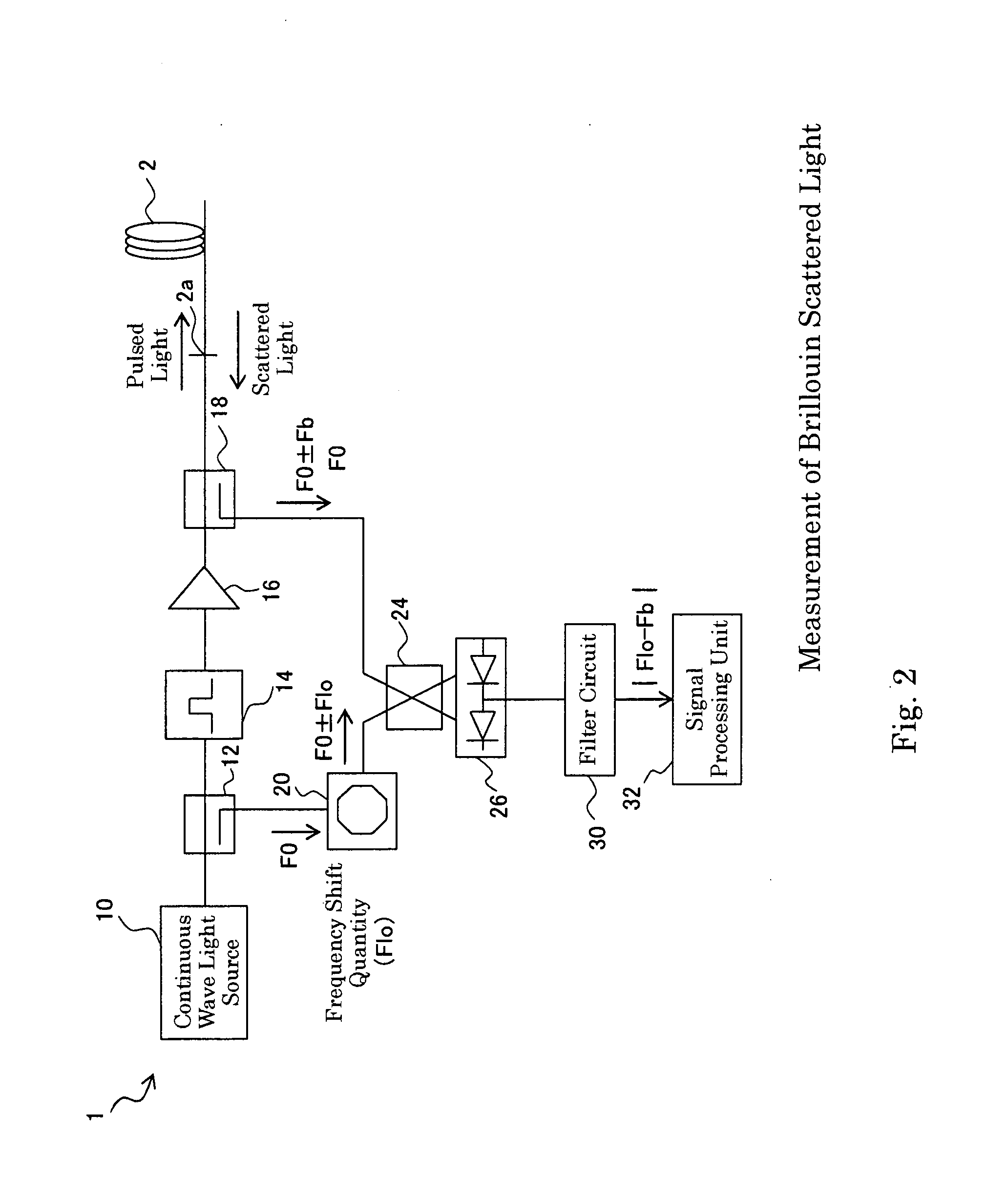
[0029]FIG. 1 is a diagram showing a configuration of a distortion measuring device 1 according to the embodiment of the present invention. The distortion measuring device 1 is connected to an optical fiber (device under test) 2. Moreover, the distortion measuring device 1 includes a continuous wave light source 10, an optical coupler 12, an optical pulse generator 14, an optical amplifier 16, an optical coupler 18, an optical frequency shifter 20, an optical coupler 24, a heterodyne optical receiver 26, a filter circuit 30, and a signal processing unit 32.

[0030] The continuous wave light source 10 generates continuous wave (CW) light. It should be noted that the optical frequency of the continuous wave light is F0. The optical coupler 12 receives the continuous wave light from the continuous wave light source 10, and supplies the optical pulse generator 14 and the optical fr...


PUM

PropertyMeasurementUnit
refractive indexaaaaaaaaaa
Brillouin scattered light spectrum recorderaaaaaaaaaa
spectrumaaaaaaaaaa

Abstract

A distortion of a device under test (such as an optical fiber) can be precisely measured. There is provided a distortion measuring device including a signal processing unit 32 having a Brillouin scattered light spectrum recording unit 322a which records a spectrum of Brillouin scattered light generated in an optical fiber as a result of supplying incident light, a Rayleigh scattered light spectrum recording unit 322b which records a spectrum of Rayleigh scattered light generated in the optical fiber as a result of supplying the incident light, a deconvolution unit 324 which derives a Brillouin gain spectrum of the optical fiber based on the recorded spectrum of the Brillouin scattered light and the recorded spectrum of the incident light, a peak frequency deriving unit 326 which derives a peak frequency at which the derived Brillouin gain spectrum takes the maximum value, and a distortion deriving unit 328 which derives a distortion of the optical fiber based on the derived peak frequency.

Description

BACKGROUND OF THE INVENTION [0001] 1. Field of the Invention [0002] The present invention relates to measurement of a distortion of an optical fiber. [0003] 2. Description of the Prior Art [0004] Conventionally, Brillouin scattered light is coherently detected by supplying an optical fiber with pulsed light generated by pulsing continuous wave light to acquire scattered light from the optical fiber (refer to FIG. 8 of Patent Document 1, for example). The coherent detection is carried out by multiplexing the Brillouin scattered light (optical frequencies: fc+fb and fc−fb) and intensity-modulated light acquired by applying intensity modulation to the continuous wave light (optical frequency: fc) at a predetermined frequency p, for example. It should be noted that the intensity-modulated light includes a carrier light component having the optical frequency fc, and side band light components having the optical frequencies fc+p and fc−p. [0005] A signal corresponding to the Brillouin sca...

Claims


Application Information

Patent Timeline
Patent Type & Authority Applications(United States)
IPC IPC(8): G01N21/00
CPCG01M11/319G01M11/3109
Inventor UKITA, JUNICHI
Owner ADVANTEST CORP
Why Eureka
Try Eureka