Electrical device measurement probes

a technology of electric devices and probes, applied in the field of temperature measurement probes, can solve the problems of reducing the lifetime of the device, affecting the accuracy of the measurement, and limited access to the transformer, and achieve the effect of facilitating the penetration of high-dielectric strength transformer oil

Inactive Publication Date: 2007-07-26
LUXTRON CORP
View PDF41 Cites 42 Cited by
  • Summary
  • Abstract
  • Description
  • Claims
  • Application Information

AI Technical Summary

Problems solved by technology

During operation, the transformer generates heat that can degrade performance and decrease device lifetime.
Because the container is sealed, access to the transformer is limited and it is not easy to remove the transformer for service and inspection due to environmental concerns.
One of the most common complaints with traditional simulated winding hot spot gauge systems is the tendency of the gauge to stick.
This problem has been noted on both new and old transformers and is a cause for concern, especially when the gauge is used for cooling control where a stuck gauge can cause excessive transformer aging or transformer failure.
In addition, WHS analog gauges typically do not provide temperature information in an electronic format that can be transmitted back through their Supervisory Control And Data Acquisition (SCADA) system.
When fiber optic temperature measurement was first introduced to the transformer industry, the fibers being used were quite fragile and required a relatively large bend radius.
Moreover, the probe tips of such known sensors remain fragile and require careful placement inside the transformer to ensure that the tip does not get crushed in the transformer manufacturing process.

Method used


Image

  • Electrical device measurement probes
  • Electrical device measurement probes
  • Electrical device measurement probes

Examples


Embodiment Construction

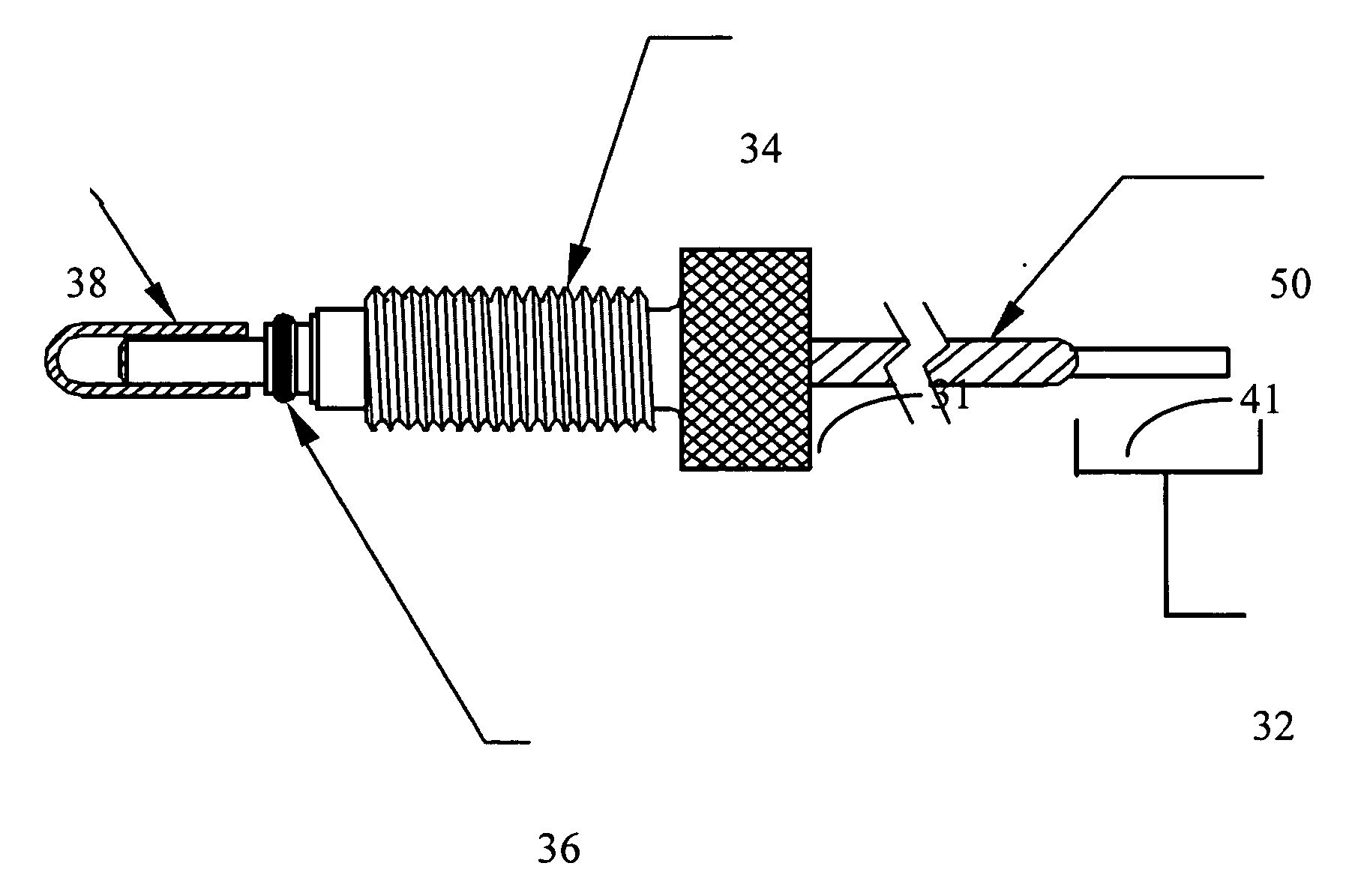
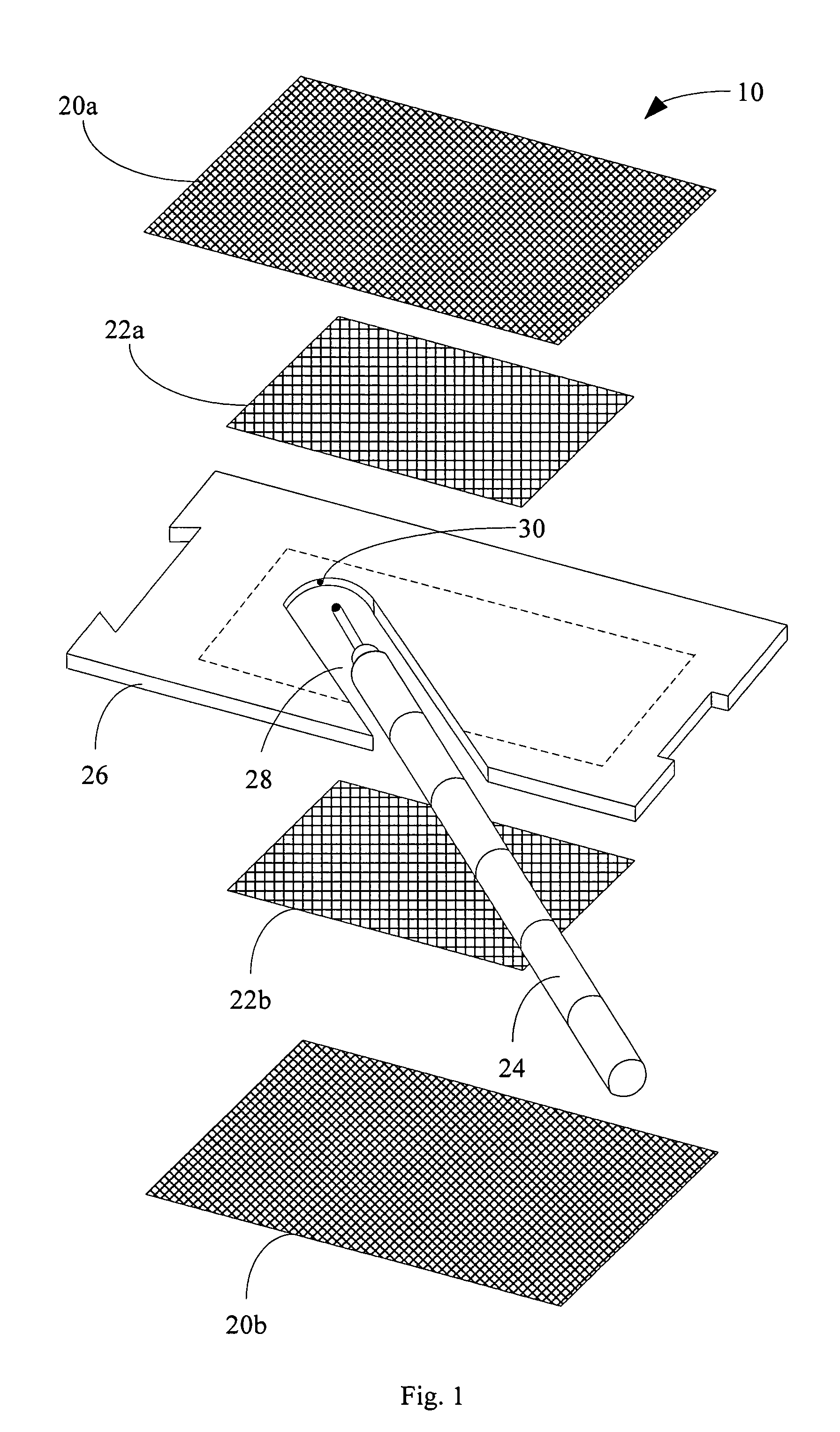
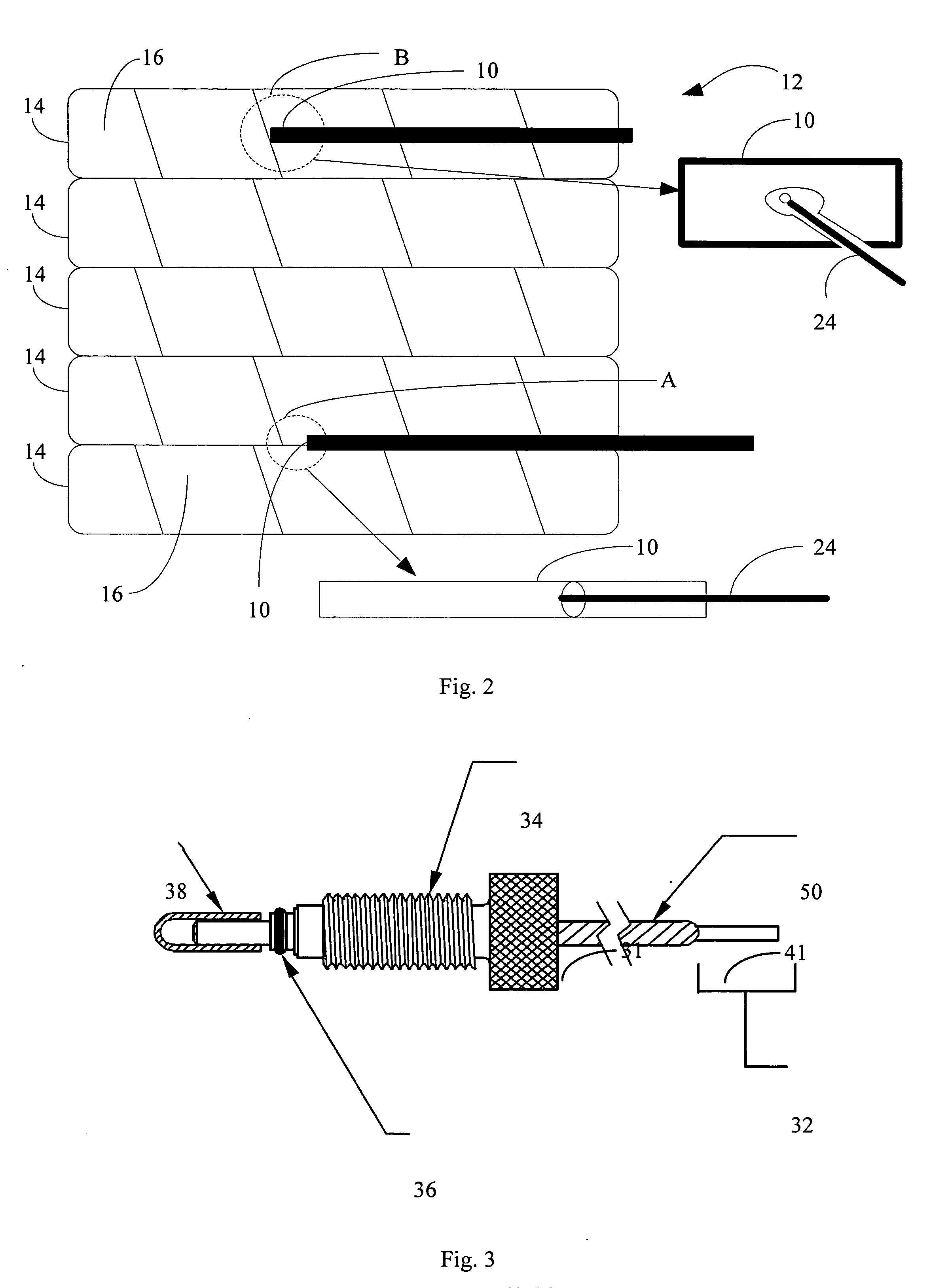
[0019] Referring now to the drawings wherein the showings are for purposes of illustrating preferred embodiments of the present invention only, and not for purposes of limiting the same, FIG. 1 is an exploded view of a fiber optic measurement probe 10 that is installed within a utility transformer. As seen in FIG. 2, transformer 12 has multiple windings 14 surrounded by insulating paper 16. The hottest spot of each winding is known as the hot spot determined by the transformer design. In some embodiments of the present invention, the probes of the present invention are placed in the vicinity of such hot spots in order to detect transformer degradation and / or to monitor hot spot temperature. In some embodiments, transformer 12 is a large transformer (e.g., greater than 100 MVA). In some embodiments, transformer 12 is a mid-size transformer (e.g., greater than 25 MVA). Probe 10 is placed between the paper 16 of adjacent windings 14 as seen in section A, or placed within the paper 16 o...


PUM

PropertyMeasurementUnit
diameteraaaaaaaaaa
temperaturesaaaaaaaaaa

Abstract

A probe for use within a high voltage and high current electrical device is disclosed. The probe comprises an optical fiber, a substrate having a slot, and a photoluminescent material. The fiber has a first and second end and is configured to convey an activation light from the first to second end. A portion of the fiber is within the slot such that the slot receives the second end of the fiber. Emission of the photoluminescent material, as a function of temperature, is known. The photoluminescent material is disposed within at least a portion of the slot that faces the second end of the fiber so that they are in optical communication with each other. A change in intensity of a luminescent light emitted back into the fiber by the photoluminescent material when the activation light is conveyed by the fiber onto the photoluminescent material provides an indication of the integrity of the electrical device.

Description

FIELD OF THE INVENTION [0001] The present invention generally relates to temperature measurement probes, and more particularly to fiber optic measurement probes capable of measuring temperature in harsh environments such as those is found within utility transformers. Some embodiments of the present invention are directed to measuring the winding hot spot temperature of transformers. BACKGROUND OF THE INVENTION [0002] Sealed electrical devices, such as transformers, are used in several industries including the utility industry. A transformer winding is surrounded by a paper material and sealed in a container filled with oil. During operation, the transformer generates heat that can degrade performance and decrease device lifetime. Because the container is sealed, access to the transformer is limited and it is not easy to remove the transformer for service and inspection due to environmental concerns. Therefore, once the transformer is sealed within the container, it must operate with...

Claims


Application Information

Patent Timeline
Patent Type & Authority Applications(United States)
IPC IPC(8): G01J5/00G01K11/00
CPCG01J1/58G01J5/0037G01J5/029G01J5/041G01J5/042G01J5/045G01R31/027G01J5/048G01J5/08G01J5/0821G01J5/0896G01K11/3213G01J5/046G01R31/62G01J5/051
Inventor HOANG, ANHSTAPLETON, TERRY
Owner LUXTRON CORP
Why Eureka
Try Eureka