Object observation system and method of controlling object observation system
a technology of object observation and object observation, which is applied in the field of object observation system and a method of controlling an object observation system, can solve the problem of difficult to accurately bring the distal end of an endoscope to a target part in a short period of tim
- Summary
- Abstract
- Description
- Claims
- Application Information
AI Technical Summary
Benefits of technology
Problems solved by technology
Method used
Image
Examples
first embodiment
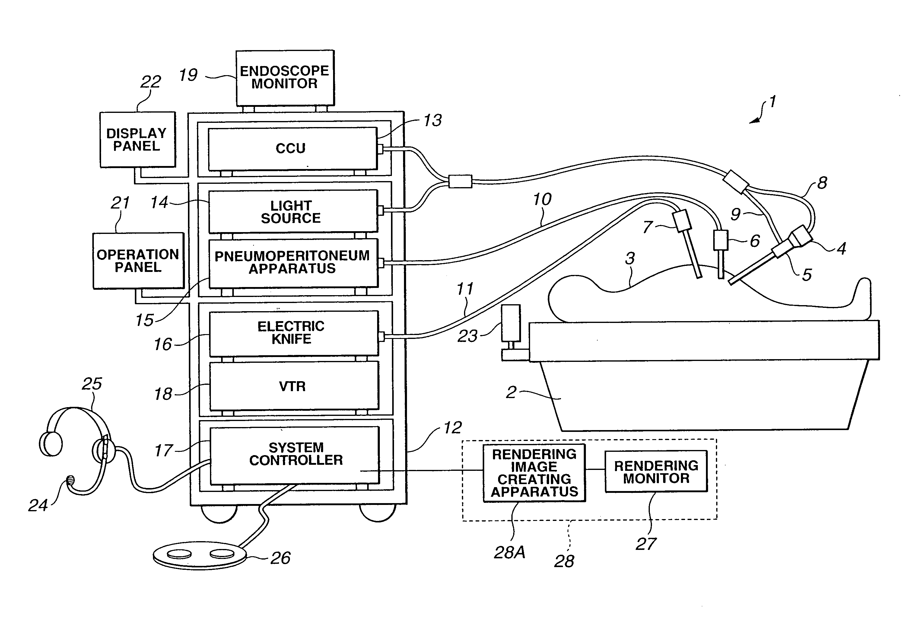
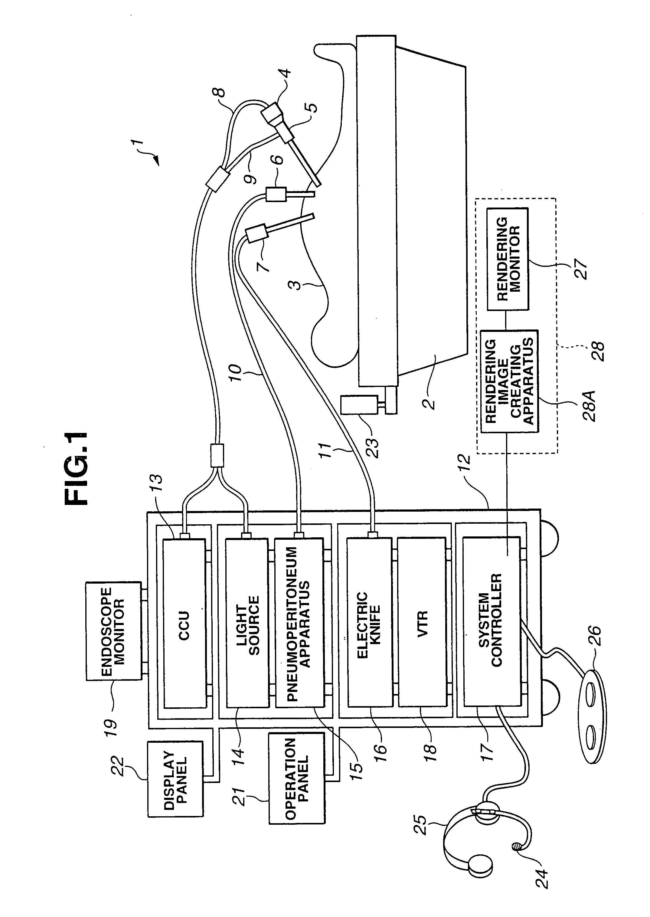
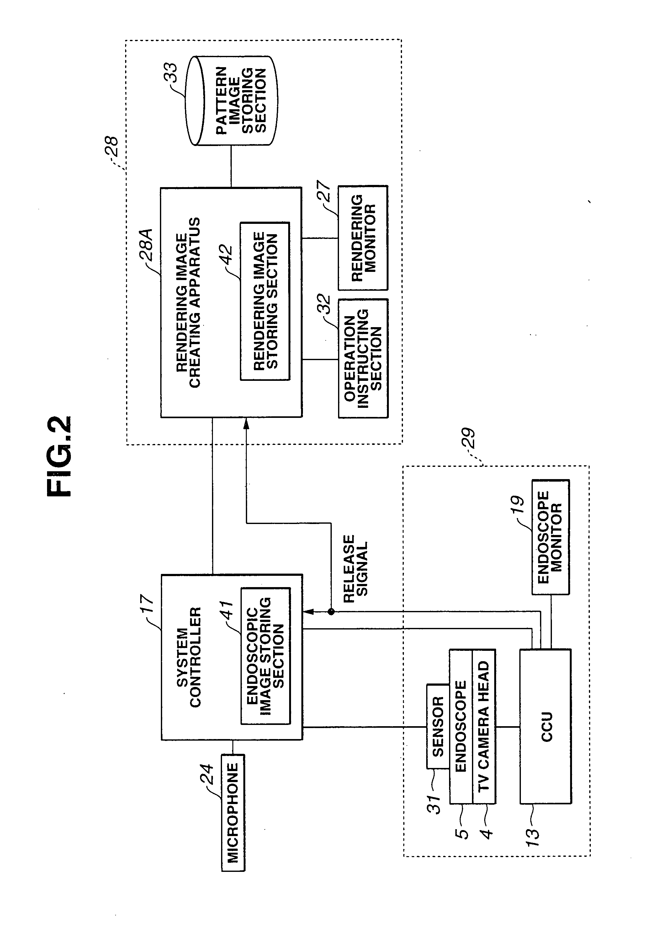
[0148] FIGS. 1 to 3 relate to a first embodiment of the invention. FIG. 1 is an entire configuration diagram showing an endoscopic surgery system according to the first embodiment. FIG. 2 is a circuit block diagram of an endoscope apparatus and rendering apparatus in FIG. 1. FIG. 3 is a control flowchart of a system controller in FIG. 1.
[0149] As shown in FIG. 1, an endoscopic surgery system 1 according to the first embodiment is an object observation system. The endoscopic surgery system 1 has a rigid endoscope (often simply called endoscope, hereinafter), which is inserted to an abdominal cavity of a patient 3, which is a body to be examined, lying on an operation table 2 through a trocar (not shown). A TV camera head 4 self-containing an image pickup apparatus is attached to the rigid endoscope 5. The endoscopic surgery system 1 includes a pneumoperitoneum guide tube 6 and an electric knife probe 7, which are inserted to the patient 3. The pneumoperitoneum guide tube 6 is used f...
second embodiment
[0181] FIGS. 4 to 8 relate to a second embodiment of the invention. FIG. 4 is a circuit block diagram of an endoscope apparatus and rendering apparatus included in an endoscopic surgery system according to the second embodiment. FIG. 5 is a control flowchart of a system controller in FIG. 4. FIG. 6 is a circuit block diagram of an endoscope apparatus and rendering apparatus showing a variation example of FIG. 4. FIG. 7 is a control flowchart of a system controller showing a variation example of FIG. 5. FIG. 8 is a display example of a synthesized image.
[0182] While, according to the first embodiment, rendering image data and the still image data of an endoscopic image are associated and are recorded in separate storing portions, rendering image data and the still image data of an endoscopic image are recorded in a same storing portion according to the second embodiment. Since the other construction is the same as the one according to the first embodiment, the descriptions thereof w...
third embodiment
[0207] FIGS. 9 to 15 relate to the third embodiment of the invention. FIG. 9 is an entire configuration diagram showing an endoscopic surgery system. FIG. 10 is a circuit block diagram of an endoscope apparatus and rendering apparatus in FIG. 9. FIG. 11 is a flowchart of image processing to be performed by a rendering image creating apparatus in FIG. 9. FIG. 12 is an image display example showing a rendering image of the inside of a body cavity around a target part, which is created by the rendering image creating apparatus in FIG. 9. FIG. 13 is a conceptual diagram showing processing pattern images extracted from a rendering image of the inside of the body cavity in FIG. 12 and a synthesized image created by synthesizing these processing pattern images. FIG. 14 is an image display example of the synthesized image in FIG. 13 after subtraction processing. FIG. 15 is a conceptual diagram in which a desired rendering image is obtained by directly instructing selective display of the sy...
PUM
 Abstract
Description
Claims
Application Information
 - R&D
- Intellectual Property
- Life Sciences
- Materials
- Tech Scout
- Unparalleled Data Quality
- Higher Quality Content
- 60% Fewer Hallucinations
Browse by: Latest US Patents, China's latest patents, Technical Efficacy Thesaurus, Application Domain, Technology Topic, Popular Technical Reports.
© 2025 PatSnap. All rights reserved.Legal|Privacy policy|Modern Slavery Act Transparency Statement|Sitemap|About US| Contact US: help@patsnap.com


