Method for generating compatible partner processes in BPEL

a technology of bpel and process, applied in the field of workflow management system, can solve the problems of inability to continue, inability to and inability to always generate a compatible partner process

Inactive Publication Date: 2007-07-26
IBM CORP
View PDF18 Cites 32 Cited by
  • Summary
  • Abstract
  • Description
  • Claims
  • Application Information

AI Technical Summary

Benefits of technology

[0028]Further advantageously, the process workflow is expressed by a hierarchical, tree-like structure, and the capability of a markup language, as for example XML, is used to map this tree-like structures into a specific format of the markup language. This helps to find an easy-to-do implementation for the basic disclosed method structure including the decision if or if not the mathematical method should be used. Thus, the mirroring procedure is further simplified.
[0029]When further reducing the number of potential combinations of sub-activities comprised of said set by applying some knowledge of the structure of the original process, then the additional advantage is achieved that the resulting partner process is as simple as possible.
[0032]The method disclosed herein solves the above-mentioned problem by generating a guaranteed behaviorally compatible and therefore runtime compliant partner process that is simple enough to be understood.

Problems solved by technology

The general challenge is to guarantee behavioral compatibility [c.f.
The original BPEL process, however, might treat him like a regular customer 225 because he might have lost his status because it was too long since he last ordered.
Now, both of the processes are waiting and none can continue on its own—a classical deadlock situation.
In the result, the behavior of both BPEL processes is not compatible.
While this approach would be based on static mapping rules of all BPEL activities, it does not always generate a compatible partner process as the initial example of FIG. 1 has proven.
Hence, the method often will yield a partner process that is often too complex to be easily understood by the partner, making it rather hard to refine it, since the process logic might be “distributed” in the generated partner process.
Thus, this prior art method has significant disadvantages for the developer and is not widely accepted, when developing a partner process.

Method used


Image

  • Method for generating compatible partner processes in BPEL
  • Method for generating compatible partner processes in BPEL
  • Method for generating compatible partner processes in BPEL

Examples


example

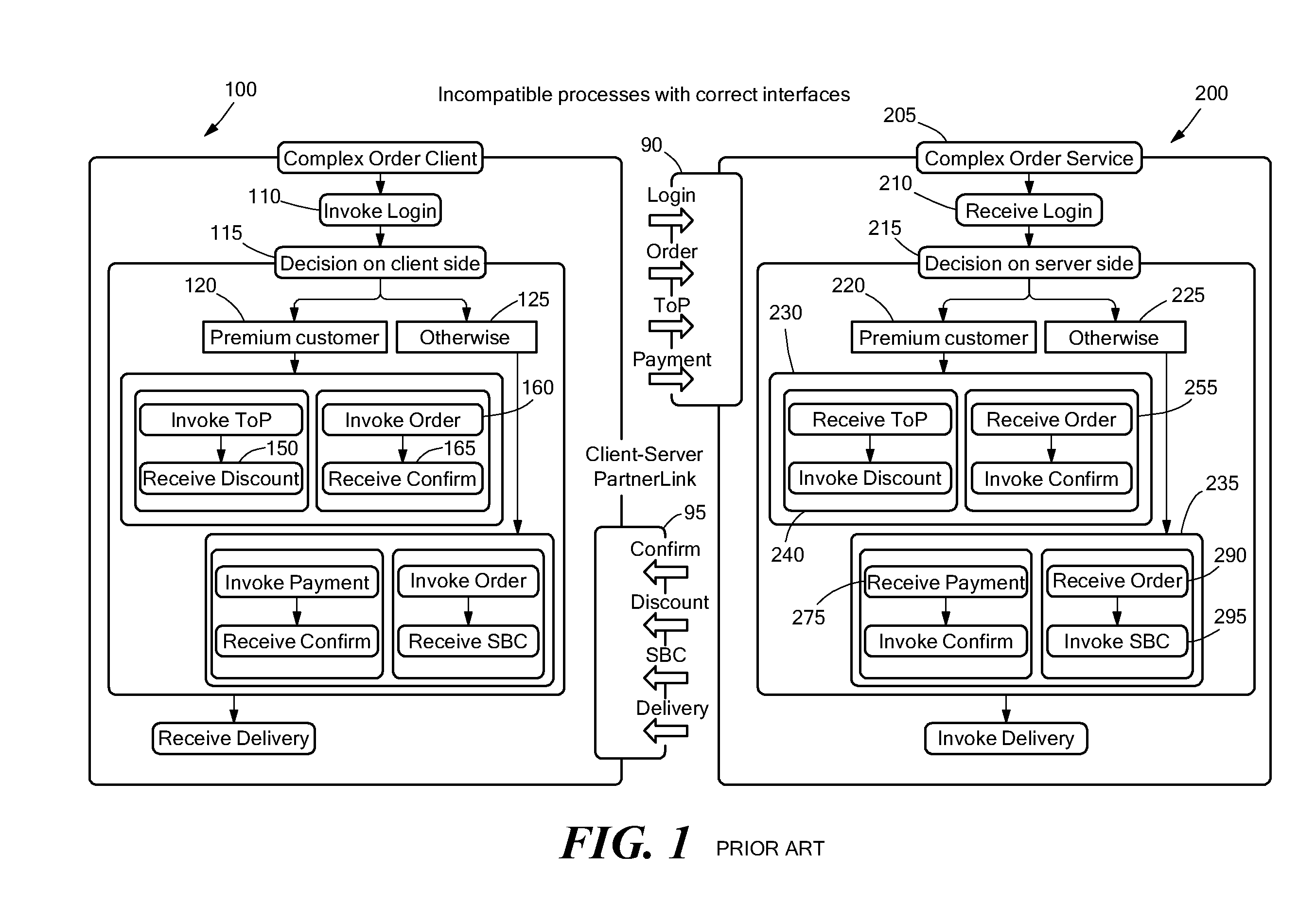
[0058]FIG. 6 illustrates the disclosed method. The left side shows the partner process 600 generated by aid of the disclosed method. It should be noted that the right side shows the original process 200, which remains unchanged in relation to FIG. 1, nor is changed by the disclosed method.

[0059]Because each BPEL process needs to be initialized by an incoming message, the disclosed approach distinguishes three cases: Either the given process initiates the partner to generate, or both processes are initiated independently by an external component, or the original process is initiated by the partner to generate. FIG. 6 depicts the last case. Consequently, the partner process itself has to be generated from outside. Hence, two activities 610, 695 realize the communication with that third, not shown party.

[0060]The first activity of the original process 200 is a sequence 205 of three activities 210, 215, and 300. As mentioned before, a sequence is mapped into a flow 615 in the structural...


PUM


Abstract

The present invention relates to a Workflow Management System or a computer system with comparable functionality (WFMS). More particularly the invention relates to a method or means for generating a runtime compliant partner process for a given original process, wherein both processes are dedicated to interact with each other. In order to provide a method for generating a runtime compliant partner process for a given original process, which is easier understandable for a process developer, it is proposed to perform the steps of:Step 1: Identifying all activities of the original process interacting with the partner process,Step 2: Determining if an activity is able to be mirrored by a mechanism supported by the business process language, e.g. BPEL,Step 2.1: If yes, generating the mirrored activity and creating a respective activity name,Step 2.1: If not, using a predetermined mathematical method for dissecting such an activity that into a set of sub-activities, which can be mirrored,Step 2.2.1: Generating a respective mirrored sub-activity and creating a respective activity name for each sub-activity,Step 2.2.2: Arranging the mirrored sub-activities according to the outcome of the predetermined mathematical method.

Description

CROSS REFERENCE TO RELATED APPLICATIONS[0001]The present application claims priority under 35 USC 119 to European Patent Application Number EP06100873.6, filed Jan. 26, 2006.FIELD OF THE INVENTION[0002]The present invention relates to a Workflow Management System (WFMS) or a computer system with comparable functionality. More particularly, the invention relates to a method or means for generating a runtime compliant partner process for a given original process, wherein both processes are dedicated to interact with each other.BACKGROUND OF THE INVENTION[0003]Workflow Management Systems (WFMS) support the development, execution and monitoring of business processes. A business process specifies a set of work items and their dependencies along with required resources and assigned roles. Within a WFMS environment, the execution of work items is triggered and monitored by the workflow engine, and even performed automatically for some work items—whereas the individual pieces of work might ...

Claims


Application Information

Patent Timeline
Patent Type & Authority Applications(United States)
IPC IPC(8): G06F9/45
CPCG06Q10/06G06F8/35G06F8/31
Inventor MOSER, SIMONHAEBICH, MARCMARTENS, AXEL
Owner IBM CORP
Why Eureka
Try Eureka